


Configuration Program
19
8.0 CONFIGURATION PROGRAM
The final step of installation may require custom configuration of your UPS using the enclosed config-
uration program. Some configuration settings may be changed only while the UPS is off. These should
be set before the UPS is put into full time service powering the critical load.
For most users operating with 120 VAC L-N and with no external batteries, the factory default set-
tings will be adequate. This manual illustrates the features available for modification, as well as the
factory default setting.
The factory default L-N setting is 120 VAC. When first powered by the AC input, the UPS will auto-
sense the utility phase angle between L1 and L2, setting the UPS to operate as either a 120/208 VAC
system (120 degrees, leading or lagging) or a 120/240 VAC system (180 degrees).
If your application requires that the L1-N, L2-N voltages be set at 100, 110, 115 or 127 VAC, the cor-
responding phase angle between L1 and L2 is restricted. The VAC settings of 100, 110 and 115 may
work only with a phase angle of 180 degrees. A VAC setting of 127 VAC will work only with a phase
angle of 120 degrees (leading or lagging).
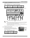
To confirm the phase angle of the utility input, measure the L1-N, L2-N and L1-L2 VAC of the utility
input that is intended for the UPS. If the measured L1-L2 voltage is equal to the average L-N voltage
times 2.0, then the phase angle is 180 degrees and the L-N VAC may be set at 100, 110, 115 or 120
VAC. The nominal L1-L2 voltages for these four settings will be 200, 220, 230 or 240 VAC, respec-
tively.
If the measured L1-L2 voltage is equal to the average L-N voltage times 1.73, then the phase angle is
120 degrees and the L-N VAC may be set at either 120 or 127 VAC. The nominal L1-L2 voltages for
these two settings will be 208 or 220 VAC, respectively.
Selecting a L-N nominal voltage that is not compatible with the L1-L2 phase angle detected by the
UPS when AC input is applied will result in a fault alarm and the UPS will not operate from utility
power.
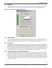
8.1 GXT2-6000RT208 Configuration Program Features
The configuration program enables the user to perform the following functions:
• Select one of five L-N output voltages to match local voltages
• Enable or disable Auto-Restart
• Select frequency converter operation with a fixed output frequency of 50 or 60 Hz
• Set the Low Battery Warning alarm time from 2 to 30 minutes
• Enable or disable the Auto-Battery test
• Set the Auto-Battery test to 7, 14, 21 or 28 days
• Specify the number of external battery cabinets connected to the UPS to adjust the remaining run
time calculations reported by Liebert software products
• Modify the shutdown setting of DB-9 pin 6 (for information on pin assignments, see 11.0 - Com-
munications)
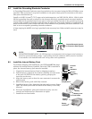
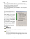
8.1.1 What You Will Need
In addition to the GXT2-6000RT208 UPS, you will need the configuration program diskette and serial
cable (beige or tan, three-wire: GND, TX, RX; straight through 2-2, 3-3, 5-5) included in the UPS
accessory box. A computer—desktop or laptop—running Windows 95
®
or later is also required to set
up and run the configuration program.
!
UPStation GXT