


Communications
31
11.0 COMMUNICATIONS
11.1 Communications Interface Port
The UPStation GXT2-6000RT208 UPS has a standard DB-9 serial port female connector located on
the rear of the UPS unit. Several signals are provided on this port and are assigned as follows:
11.1.1 DB-9 Interface Port
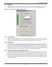
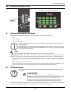
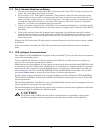
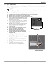
Using the following directions to attach the smaller enclosed ferrite
bead clamp to the communication cable as shown at right:
1. Open the ferrite bead.
2. Place the communication cable inside the ferrite bead groove.
3. Position the ferrite bead as close as possible to the end of the cable
that connects to the DB-9 connector of the UPS.
4. Close the ferrite bead so that the ferrite bead’s case snaps closed
with the cable routed through the ferrite bead’s case.
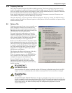
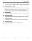
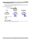
11.1.2 Communications SNMP Web Card SNMP Adapter
Attach the larger enclosed ferrite bead clamp to the network
cable, see illustration at right, using the following directions:
1. Open the ferrite bead.
2. Place the network cable inside the ferrite bead groove.
3. Wrap the cable once around the ferrite bead.
4. Position the ferrite cable as close as possible to the end of
the cable that connects to the UPS.
5. Close the ferrite bead so that the ferrite bead’s case snaps
closed with the cable routed through the ferrite bead’s case.
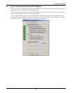
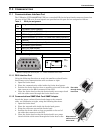
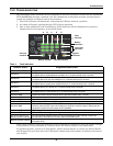
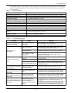
Table 3 DB-9 pin assignment
DB-9
Pin
Assignment Description
1 Low Battery (open collector)
2 UPS TxD (typically RS-232 levels)
3 UPS RxD (typically RS-232 levels)
4 Remote Shutdown (5-12VDC, 10-24mA max; battery operation)
5 Common
6 Remote Shutdown (short to pin 5); all modes of operation
7 Low Battery (open emitter)
8 Utility Fail (open emitter)
9 Utility Fail (open collector)
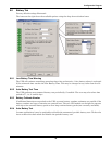
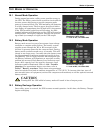
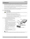
Pin Assignment Collector to Emitter*
* Maximum voltage and current on pins 1, 7, 7 and 9 are 60VDC and 10.0 mA
54321
6789
(-)
(+)
330 Ohms
Open
Collecto
r
Open
Emitter
Run cable
through ferrite
bead case
Wrap network
cable around
ferrite bead