Controls and Indicators
29
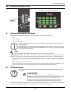
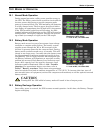
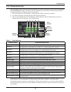
9.3 L1 & L2 Load Level Indicators (Two Rows of Indicators: 4 Green, 1 Amber)
The Load Level indicators display the approximate electrical load placed upon both output legs of the
UPS at all times. Each indicator represents an approximate 25 percent increase in load. For optimum
utilization of the UPS, distribute L-N loads to approximately balance the loads on L1 and L2.
9.4 Battery Level Indicators (5 Green)
The Battery Level indicators display approximate battery capacity at all times. Each indicator repre-
sents an approximate 20 percent increase in battery capacity.
The UPStation GXT2-6000RT208 is equipped with automatic and remote battery test features. The
automatic test occurs every 14 days (this option is user-configurable) if utility has not been inter-
rupted. Should the battery fail this test, the red Fault indicator along with the A and C diagnostic
indicators will illuminate and an alarm will sound (refer to 13.0 - Troubleshooting). The remote
test feature functions with MultiLink 3 software and can remotely initiate the battery test.
9.5 Fault Indicator (Red)
The Fault indicator is illuminated if the UPS has detected a problem. Also, one or more of the Battery
Level indicators may be illuminated (refer to 13.0 - Troubleshooting section).
9.6 Bypass Indicator (Amber)
The Bypass indicator is illuminated when the UPS is operating from bypass power. An alarm will
sound indicating the UPS detected a problem or the manual bypass function has been activated.
9.7 UPS ON Indicator (Green)
The UPS ON indicator is illuminated when the UPS inverter is operating and supplying power to
your connected loads.
9.8 Battery Indicator (Amber)
The Battery indicator is illuminated when the UPS is operating on battery.
9.9 AC Input Indicator (Green)
The AC Input indicator is illuminated when utility power is available and within the input specifica-
tions.


