8
2.5 Connecting Multiple ServerSwitches
In each cascade, there is a master unit, and one or more auxiliary units. The users are
directly attached to the master unit, and can control and access all the auxiliary units
through that master unit. There may be up to 9 auxiliary units in a cascade along with
one master unit, allowing the two users to control 80 CPUs.
To connect several ServerSwitches in a cascade, first select the unit that will be the
master unit. The monitors and keyboard/mouse sets for the users will be directly
attached to this unit. Be sure that the monitors are identical or at least have compatible
operating modes, as user B will most likely not be able to use his monitor if the monitors
are incompatible.
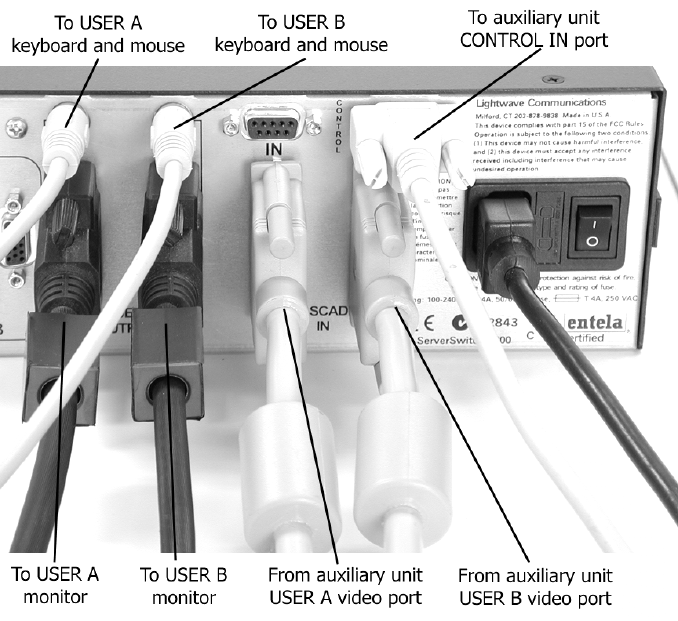
Attach a DB9 serial data cable to the CONTROL OUT port on the back of the master
unit. Be sure to secure the cable to the port using the screws on the cable. Attach the
serial data cable from the master unit to the CONTROL IN port on the first auxiliary unit
in the cascade, and secure the cable to the port. Attach the serial cable from the
CONTROL OUT port of the auxiliary unit closest to the master in the cascade (the
upstream unit) to the CONTROL IN port of the auxiliary unit further away from the
master in the cascade (the downstream unit), and repeat until all units in the cascade
are connected. The last unit in the cascade will only have a serial cable attached to the
CONTROL IN port.
Cable connections to a cascade master unit


