


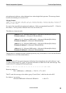

Danish Interpretation Systems Technical Specifications
Printed in Denmark
39
microphone unit addresses, where delegates have acknowlegded their presence. The message format
has the same meaning as in section 3.4.4.
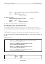
Message format:
<START> 'c' <ID> <MSB addr> <LSB addr> <58> <8> <Presence MSB addr1> <Presence LSB addr1> <Presence MSB
addr2> <Presence LSB addr2> <Presence MSB addr3> <Presence LSB addr3> <Presence MSB addr4> <Presence
LSB addr4> <CRC> <STOP>
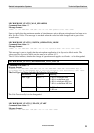
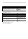
For each of the 4 possible microphone unit addresses, 16 bits are transmitted from the CU – 12 bits for
the address, 1 bit for presence indication and 3 bits are unused (=0):
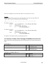
The addresses of present units:
The presence of a delegate has been confirmed positively only, if the address is not 0 and the Presence
of Address bit is set for the related address.
Example:
Imagine, that the CU has received presence indications from microphone units with addresses 1 and
34. And, assume that the CU ‘packs’ the presence indications of both units in the same message. That
results in the CU sending the following message:
<START> 'c' <ID> <15> <173> <58> <8> <0> <17> <2> <0> <0> <0> <0> <18> <CRC> <STOP>
Receiving address is:
256 * <MSB addr> + <LSB addr> = 256*15 + 173 = 4013
The CU sends this message to the address group ‘Control Units’, which has the value 4013.
For Address 1 we receive:
<Presence MSB addr1><Presence LSB addr1> = <0><17>
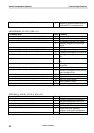
Address 1
= 16* <Presence MSB addr1> + <Presence LSB addr1[Bit3-Bit0]>
Presence Address 1 = <Presence LSB addr1[Bit4]>
Address 2 = 16* <Presence MSB addr2> + <Presence LSB addr2[Bit3-Bit0]>
Presence of Address 2 = <Presence LSB addr2[Bit4]>
Address 3 = 16* <Presence MSB addr3> + <Presence LSB addr3[Bit3-Bit0]>
Presence of Address 3 = <Presence LSB addr3[Bit4]>
Address 4 = 16* <Presence MSB addr4> + <Presence LSB addr4[Bit3-Bit0]>
Presence of Address 4 = <Presence LSB addr4[Bit4]>