


Danish Interpretation Systems Technical Specifications
Printed in Denmark
44
5 Controlling Microphones
The purpose of this section is to give a short summary of how the methods described in the rest of the
manual can be used to control the system.
5.1 CRC Calculation
5.1.1 CU Reset message
When the CU is powered up, the very first control message to send to the external control unit is a ‘CU
reset’ message.
It has the format:
<START> ‘r’ <ID> <CRC> <STOP>
The CRC-checksum is calculated from the bytes ‘r’ <ID>
With ID=0, the CRC becomes 136 and the complete message gets the following contents:
[252] [114] [0] [136] [253]
5.1.2 Entering binary microphone control mode
The binary microphone control mode is entered by the ‘Change Mode’ control message. It has the
following format:
<START> ‘m’ <ID> ‘c’ ‘m’ <CRC> <STOP>
With ID=0, the CRC becomes 101 and the complete message gets the following contents:
[252] [109] [0] [99] [109] [101] [253]
See also 6.1.1.
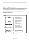
5.2 Registering with the CU
Basically, there are two different ways to get the communication between the CU and an external
control unit up and running. These scenarios are described below.