


On-Screen Display
OSD Operation
MN102H75K/F75K/85K/F85K LSI User Manual Panasonic Semiconductor Development Company
157
Panasonic
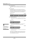
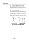
■ Graphics layer
The graphics layer contains tiled images. In the 16-color mode, each 4-bit dot on
a tile can display one of 16 colors. Each tile can use either of two available color
palettes, allowing a total of 32 colors in one display. The graphics layer also
supports 2-, 4-, and 8-color modes. All the tiles in a single display screen must be
in the same color mode. (For instance, an 8-color-mode tile cannot be displayed
at the same time as a 16-color-mode tile.) The size of one tile is 16W x 16H
pixels in standard mode and 16W x 18H pixels in extended mode.
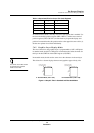
■
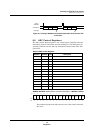
Cursor layer
The cursor layer displays an icon indicating the position of the next entry. One
display screen displays only one cursor (tile). The ROM data and color palettes
for the tile are the same as those of the graphics layer. The size of one tile is 16W
x 16H pixels in standard mode and 32W x 32H pixels in extended mode.
When you are not using the
DAC, set the COMP and IREF
pins for the DAC to H.
7.5.4 Output Pin Setup
To set up the output pins, enable the OSD output pins in the I/O registers. Select
DAC or digital output for RGB and YM. Set the YS polarity.
7.5.5 Microcontroller Interface
The microcontroller writes display data to be sent to the OSD control registers
and the VRAM, which is assigned to internal RAM space. The control registers
(CRAMEND and GRAMEND) hold the end address of the data in the VRAM.
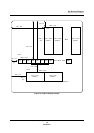
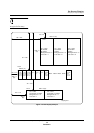
7.5.6 VRAM
After a reset clears, the system
clock supply to the OSD stops.
To operate the OSD, you must
first set the OSDPOFF bit of
PCNT0 (x’00FF90’)to 1.
Display data stored in the VRAM transfers automatically (through) a DMA
transfer) from the internal RAM to the OSD as the display approaches its
specified position. The microcontroller is suspended while the data is transferred
on the bus. See section 7.10, “DMA and Interrupt Timing,” on page 185, for
more information on this timing.
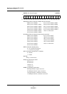
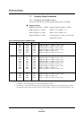
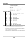
The two MSBs of the transferred data contain one or more of the following ID
codes:
■
Text layer
1. Character code CC
2. Color control code (normal mode) COL
3. Color control code (closed-caption mode) COL
4. Repeat character/blank code CCB
5. Character horizontal position code CHP
6. Character vertical position code CVP
■
Graphics layer
1. Graphic tile code GTC
2. Graphics horizontal position code GHP
3. Graphics vertical position code GVP