


Timers
16-Bit Timer Description
Panasonic Semiconductor Development Company MN102H75K/F75K/85K/F85K LSI User Manual
88
Panasonic
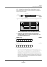
4.7 16-Bit Timer Description
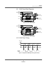
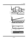
The MN102H75K/85K contains two 16-bit up/down timers, timers 5 and 6.
Associated with each timer are two compare/capture registers that can capture
and compare the up/down counter values, generate PWM signals, and generate
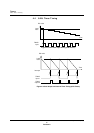
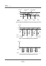
interrupts. The PWM function has a double buffering mode that causes cycle and
transition changes to occur at the beginning of the next clock cycle. This prevents
PWM signal losses and minimizes waveform distortion during timing changes.
Underflow interrupts can only
occur during down counting.
Timers 5 and 6 can serve as interval timers, event counters (in clock oscillation
mode), one- or two-phase PWMs, dual capture inputs, dual two-phase encoders,
one-shot pulse generators, and external count direction controllers. The clock
source can be the internal clock, the external clock, or the TM0UDIR or
TM1UDIR signals from the 8-bit timers.
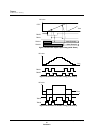
Note: B
OSC
= 24 MHz
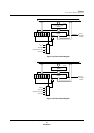
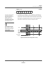
Figure 4-14 Block Diagram of 16-Bit Timers
TMnIC
2-phase encoding
Match
CLR
Match
Capture
Capture
Up/down counter
TM0UDIR
TM1UDIR
B
OSC
/4
TMnIB
TMnIA
TMnOA
TMnOB
16-bit compare/capture A
16-bit compare/capture A
TQ
TQ
R
S
Q