


Marathon Technologies Corporation 11
FTvirtual Server and Blade Configuration
Each Endurance FTvirtual Server configuration is comprised of two blades.
Following installation of the Endurance software each will function as a
CoServer to create the FTvirtual Server environment.
Depending upon the specific configuration, a 14 slot BladeCenter chassis
can support a total of 7 Endurance FTvirtual Servers (2 slots per FTvirtual
Server), using single-slot blades configured with one or two on-board disks
and four network adapters. If each blade is configured with four network
adapters and a piggy-backed SCSI Expansion Unit option for increased
storage capacity, a total of 3 Endurance configurations (4 slots per FTvirtual
Server) may be supported.
It is important to note that the chassis slot position of a blade has no impact
on its function. After an Endurance system has been established, the
blades can be moved to any chassis slot and located in any order. Data
communications between Endurance configured blades is controlled by IP
addresses, which are unique to a blade and FTvirtual Server blade pair.
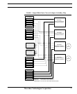
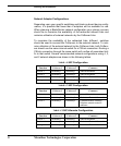
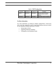
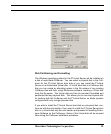
Identifying Network Components
To help simplify Endurance software installation it is suggested that you first
create a chart that maps blade configured network adapters to their corre-
sponding ethernet switchbay connection. Since this mapping may vary
across blade (HSxx) models, it is important that you identify these connec-
tions prior to installation. Later, during the network setup phase of the instal-
lation you will be able to correlate a CoServer assigned networking role to
its corresponding adapter and ethernet switchbay connection.
A specific network adapter must be identified by its unique PCI bus location
in the system in terms of:
“PCI bus b, device d, function f”
Switchbays may be identified from the back of the BladeCenter cabinet by
the number of the particular bay they reside in.