


LTRx-512 Installation and User’s Guide
8
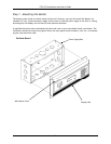
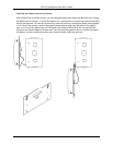
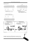
Step 2 – Wiring the Master
Wire the display panel and power relay units for bell control and clock synchronization. Refer to the
diagrams in Appendix C2 for more details. Until you complete this part of the wiring, do not turn on
the AC power to P4, and keep the power/relay unit’s toggle switch turned “OFF”
(Note: The LTR4-512 does not contain Terminal Block P3)
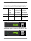
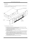
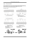
Power Supply – LTR8
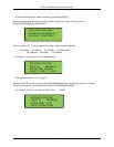
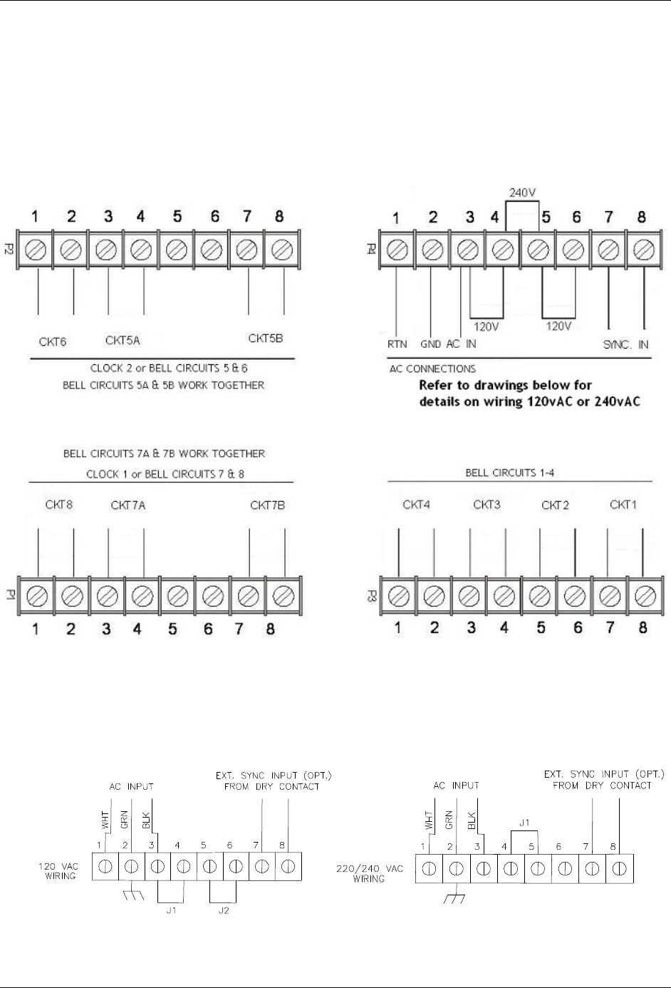
TERMINAL BLOCK ‘P4’
WIRING THE LTR8-512 FOR 120VAC
(nom.) OPERATION
J1 installed between 3 & 4 and J2
installed between 5 & 6
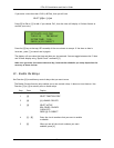
TERMINAL BLOCK ‘P4’
WIRING THE LTR8-512 FOR 220/240VAC
(nom.) OPERATION
J1 installed between 4 & 5