


LTRx-512 Installation and User’s Guide
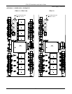
Wiring Diagrams
55
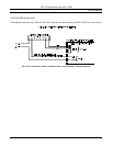
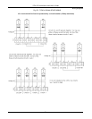
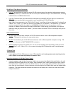
RS-485 Sync Time Device Connection
•
Sync In: Terminal block pair used to receive RS-485 synchronization from another Lathem Master product
or radio sync device, or transmit the LTRx-512’s own sync commands to up to 31 RS-485 devices, including
Lathem Masters and DDC4R Wall Clocks
•
Sync Out: Terminal block pair used to buffer and repeat a received RS-485 sync signal, or transmit the
LTRx-512’s own synchronization commands to up to an additional 31 RS-485 devices
Note: When first powered on, the LTRx-512 will “listen” to the Sync-In line to determine if it should be a
“Master” or a “Slave”. If it does not receive a time update for 15 minutes, it will assume it is a “Master”
and start transmitting the time signal on the RS485 Synchronization line, every minute. It will re-
evaluate it’s Master/Slave status every day at 00:00 Hours. When setting up the Master/Slave system,
make sure that you power on the “Master” first and connect the other LTRx-512 to the Sync-Out port on
that clock.
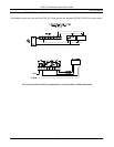
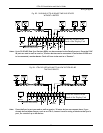
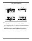
Host Communications
•
RS-232: Three terminal block contacts for RS-232 communications with an IBM-compatible computer
running LTR MasterLink software for easy system setup
•
RS-485: Terminal block pair for RS-485 communications with an IBM-compatible computer running LTR
MasterLink software and SWIFT (RS485-RS232 converter)
•
Modem: Modular connector for modem use. You can use the optional internal modem to dial out to the
“Atomic Clock” at Ft. Collins, CO, or for a remote site using the LTR MasterLink and Terminal Manager
software
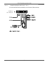
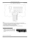
12 Volt AC Out
•
A non-regulated 12 Volt 250ma power source. This circuit is not fused seperately and attaching devices
with a higher current load may damage the Master Clock.
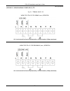
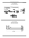
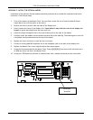
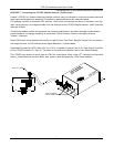
Mounting the Master with Hidden Power Supply
•
Using the optional eight (8) foot Connection Cable, you can mount the Display Unit semi-flush on the wall
and place the Power Supply Box in the ceiling, floor or behind a wall. When attaching this cable, remove
the standard short cable and connect the 8 foot cable to the power supply board with the cable moving
away from the circuit board. Connect the other end to the back of the Display Unit using the ribbon cable
connector. The cable should lead towards the bottom of the Display Unit. Attach the strain releif cable
clamps at each end.