


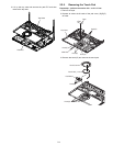
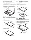
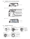
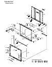

3.3. Installation and Line processing of Speaker
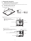
Solder
Speaker Fixation Ring
Match case
sign to the center in the terminal of the speaker.
2
2.5mm From the rib to the terminal
The double coating part of
the cable according to the ditch of the case
The cable is not loosening between the rib and the pin.
Put according to 4 ribs.
Putting of speaker fixation ring
Processing of speaker cable
Putting of speaker box
Black line
Red line
Touch the boss
Speaker Cable
Putting of speaker box
Touch the Case’s wall
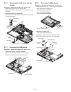
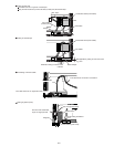
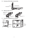
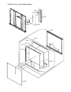
3.4. Assembly of Touch Pad
The hooks are hooked
The hooks are inserted
Pad Cover
Putting of pad cover
It is confirmed that all
LED lenses fit in the
hole of the pad cover
Pin for positioning
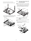
Touch Pad
The touch pad
is put
Putting of touch pad
Touch Pad
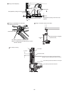
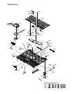
PAD FFC
Insertion of PAD FFC
PAD FFC is
inserted in the
connector.
(Direction where
the reinforcement
version is seen)
Sets in the dent
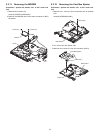
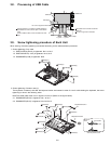
PAD sheet
Putting of PAD sheet
This line must
become vertical
After putting of the
PAD sheet, the
Flaking off paper is
peeled off
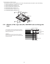
Pad button
Latch is inserted in the top case(4 places)
Installation of pad button
Puted in the gasket
ditch
Inserted in the
positioning pin
3-4