


Installation
Maxtor Atlas 10K III 3-11
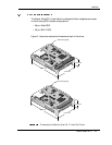
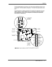
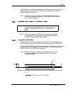
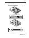
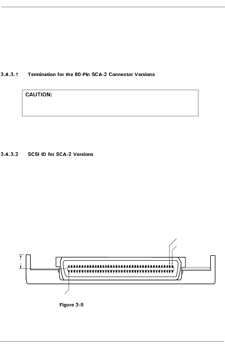
Use Figure 3-5 to locate the appropriate pins for configuring the drive. Note that
Figure 3-5 does not call out each of the 80 pins on the connector, but rather
illustrates the layout of the pins.
Note: The SCA-2 Connector version of the disk drives does not provide
the following jumper configuration: TERMPWR, Active Termina-
tion, or Write Protection.
Note: Refer to your system or SCSI controller documentation regard-
ing any additional recommendations regarding drive placement
on the SCSI bus and SCSI bus termination.
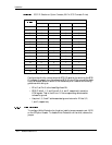
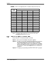
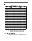
Each SCSI device on the bus must have a unique SCSI ID number assigned to it.
The drive can be configured for SCSI ID numbers that range from 0 through 15.
Configure the SCSI ID by providing the proper open or ground signal inputs to the
referenced pins of the drive’s 80-pin new version SCA-2 connector (Figure 3-5).
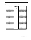
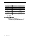
Refer to Table 3-2 for SCSI ID pin assignments.
Note: Refer to your system or SCSI controller documentation for spe-
cific recommendations about assigning SCSI ID numbers for
your specific system.
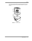
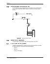
Pin Locations on SCA-2 Connector
These versions of Maxtor Atlas 10K III disk drives cannot be
configured to provide bus termination. Therefore, be sure to
properly terminate the SCSI bus on which this drive is in-
stalled.
4.60±0.50
Pin 1
Pin 80
Pin 2