


16
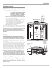
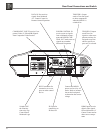
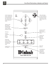
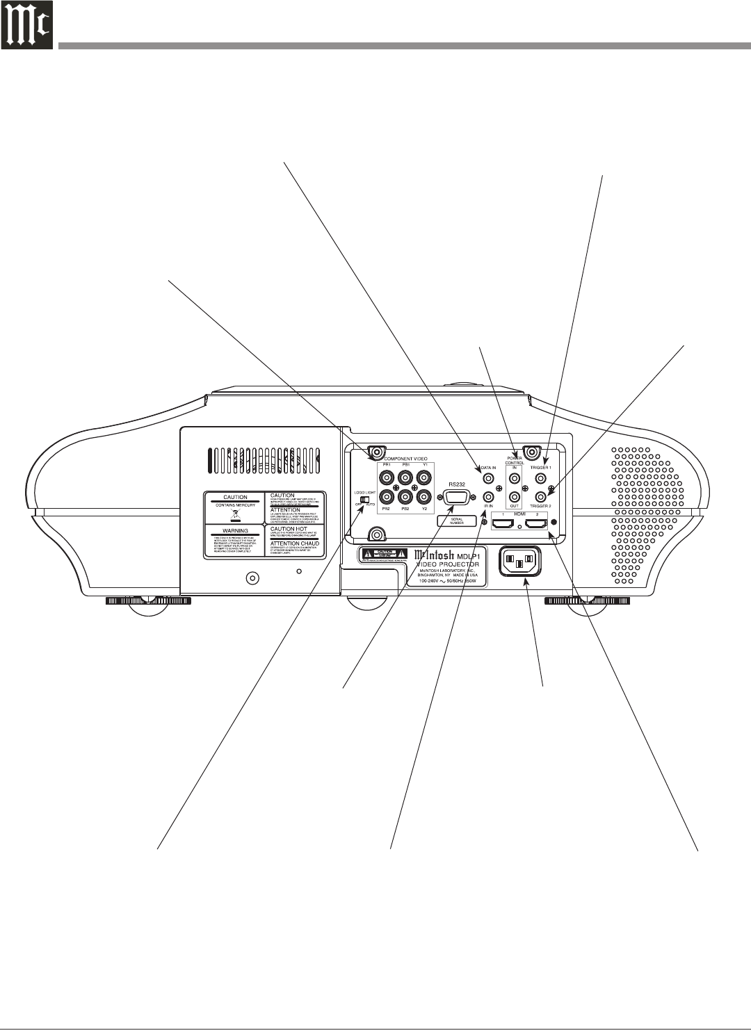
Connect the MDLP1
power cord to a live AC
outlet. Refer to informa-
tion on the back panel
to determine the correct
voltage
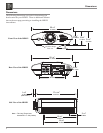
COMPONENT INPUTS receive Com
-
ponent Video (Y, PR and PB) Signals
from Component Video Sources
RS232 connector for
connection to a com-
puter or other control
device
HDMI Inputs receive
digital video signals
from a McIntosh A/V
Control Center and/or
other source compo
-
nents
TRIGGER 1 Output
sends a Turn-On signal
to other components
when the MDLP1 is
switched On
DATA IN Port receives
signals from McIntosh
A/V Control Center for
Remote Control Operation
TRIGGER 2 Output
sends Turn-On
signals to other com-
ponents and may be
assigned to activate
when a specific as-
pect ratio is selected.
POWER CONTROL IN
receives turn-on signals
from a McIntosh compo-
nent and POWER CON-
TROL OUT sends turn-on
signals on to another
McIntosh Component
IR INput for
connecting an
IR Receiver
Switches Off
the illumina-
tion to the Top
Control Panel
McIntosh Logo
Rear Panel Connections and Switch