


4.0 ARCHITECTURE
There are two types of functional elements on the CIO-SSH16; differential amplifiers
and a sample & hold chips (LF398). Together they provide differential input and
amplification for up to 16 channels of simultaneous sampling signal conditioning.
This section contains information on the following subjects:
Amplification. Gains & signal diagram.
Sample & Hold. Signal diagram, triggering, timing diagram.
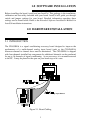
4.1 ANALOG INPUT
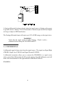
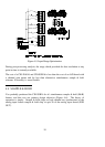
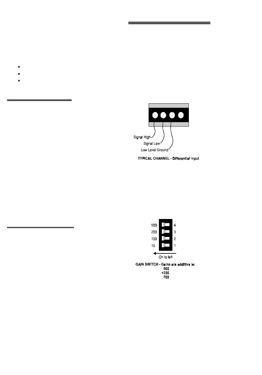
Analog signal connections are made at screw
terminals located along the edge of the board.
These screw terminals will accept 12-22 AWG
wire and are of the high quality 'clamp' type
(Figure 4-3).
Each input channel has three terminals; signal
high, signal low and ground.
Figure 4-3. Analog Input Connection
The inputs are fully differential. There are two possible signal connections to a
differential input which are described in the section on analog electronics.
The screw terminal inputs feed directly into a differential amplifier, part no. IAN110.
There are no passive components on the trace between the screw terminal and the
IAN110.
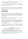
4.2 AMPLIFICATION
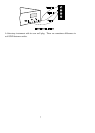
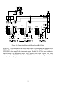
Each channel is equipped with an INA110
differential amplifier, the gain of which is
controlled by a four position DIP switch (S1-S16
for channels 15 to 0; S1=ch15, etc.). The gain
settings are additive so a total of 16 different gains
(including 1) are possible..
Figure 4-4. Gain Switches
We suggest that the analog input board be configured for a range of +/-5V bipolar or 0
to 10V unipolar and that a CIO-SSH16 gain be chosen that amplifies your sensor
signal to that level. Fully amplifying the signal at the CIO-SSH16 provides a high
8