


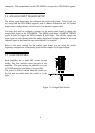
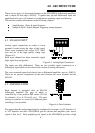
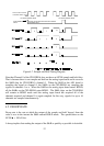
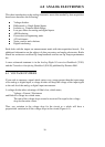

Figure 4-7. Sample and Hold Timing Diagram
Note that Channel 0 of the CIO-SSH16 does not have an LF398 sample and hold chip.
That is because there is one sample and hold on the analog input board and it serves as
the S&H chip for CIO-SSH16’s channel 0. When the S&H on the A/D board is
sampling the signal on channel 0, the S&Hs on the CIO-SSH16 are sampling the
signals on channels 1 to n. When the S&H on the analog input board enters HOLD,
all the S&Hs on the CIO-SSH16 enter HOLD. The S&H chips on the CIO-SSH16
will remain in HOLD mode until the analog input board has acquired all of the
channels required and channel 0 is again sampled. In this way, signals for up to 16
channels are sampled simultaneously.
4.5 DROOP RATE
Droop rate is the rate at which the output of the sample and hold 'droops' from the
value it was in the instant the S&H entered HOLD mode. The specification on the
LF398 100 uV/ms.
A droop implies that reading the output of the S&H as quickly as possible is desirable.
12
ANALOG INPUT BOARD’S
ON-BOARD SAMPLE-HOLD
CIO-SSH16 SAMPLE MODE CIO-SSH16 SAMPLE MODE
CIO-SSH16 HOLDS WHILE ANALOG IN BOARD
ACQUIRES DATA
LF398 SAMPLE/HOLD
PIN 26