


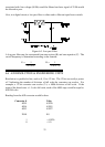

specify the conditions under which the specification was made. That means the PC,
the PC's power supply and the connection to the front end.
Put some very good components on a circuit board and place that board in a PC and
the system will be less accurate than the individual components. Some 12-bit A/D
boards with the same components as a CIO-DAS16 have as little as nine bits of
accuracy, due to board noise.
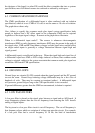
The system specification for the CIO-SSH16 and CIO-DAS16 is +/- 1 LSB. That
means that if an analog input is tied to ground and the CIO-SSH16 is on a bipolar
scale, the reading will be 2048 90% of the time. The other 10% of the readings will
be 2047 and 2049, which is +/- one count (LSB). This is actually not very different
from the component specifications.
You can verify this by grounding an analog input channel to LLGND, taking 1000
readings, then plotting a histogram of those readings. (If your histogram is not +/- 1
LSB, check the +/- 12V PC power supply voltages.)
6.9.2 SIGNAL WIRE NOISE
Signal wires, especially single-ended inputs, are subject to EMI and RFI, both of
which can induce noise on the wires carrying the transducer signal to the CIO-DAS16
board. Fortunately, signal wire noise is often localized and can be reduced by
repositioning the signal wire run and/or shielding.
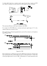
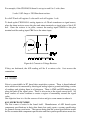
To check for signal wire noise, first, short analog channel 0 to low level ground* at
the connector and take 10,000 samples and plot the histogram. This is the best the
signal can be and is what you will try to achieve with the signal wires in place.
After you have an ideal case histogram, remove the short between analog input 0 and
low level ground. Attach the signal wires to the CIO-DAS16 board inputs and run
them to the sensor. Do not connect the sensor yet, just short the analog input(s) to
LLGND.
Take data for the histogram and compare it to the best case data taken previously. If it
shows noise, you can try to eliminate the noise by doing the following:
Move the signal wires, trying to locate a 'quiet' run.
Use a shielded twisted pair as the signal wire. Attach the shield at the PC
end only. If the shield is attached at both the PC and the sensor it may create
a ground loop and add to signal interference.
6.9.3 SENSOR NOISE
When the signal wires have been tested and characterized for signal quality, connect
the sensor and provide a known level to the sensor (ice bath for temp., etc.) then take
data for the histogram plot. If additional noise has been introduced by the sensor
which exceeds the sensor specifications, you can try moving the sensor or electrically
isolating it from the device it is measuring.
24