


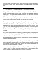
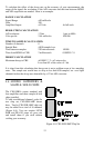
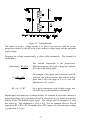
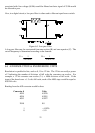
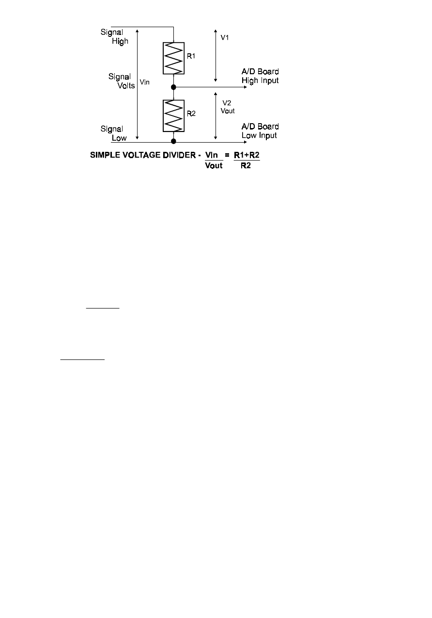
Figure 6-1. Voltage Divider
The object in using a voltage divider is to choose two resistors with the proper
proportions relative to the full scale of the analog or digital input and the maximum
signal voltage.
Dropping the voltage proportionally is often called attenuation. The formula for
attenuation is:
For a given attenuation, pick a handy resistor and
call it R2, the use this formula to calculate R1.
R1 = (A-1) * R2
For example, if the signal varies between 0 and 20
volts and you wish to measure that with an analog
input with a full scale range of 0 to 10 volts, the
Attenuation is 2:1 or just 2.
2 = 10K + 10K
10K
The variable Attenuation is the proportional
difference between the signal voltage max and the
full scale of the analog input.
Attenuation = R1 + R2
R2
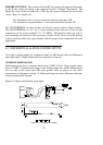
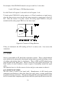
Digital inputs also make use of voltage dividers, for example, if you wish to measure a
digital signal that is at 0 volts when off and 24 volts when on, you cannot connect that
directly to the CIO-DAS16 digital inputs. The voltage must be dropped to 5 volts
max when on. The Attenuation is 24:5 or 4.8. Use the equation above to find an
appropriate R1 if R2 is 1K. Remember that a TTL input is 'on' when the input voltage
is greater than 2.5 volts.
17