


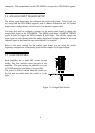
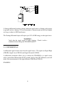
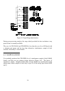
The SSH16 requires 1 Amp of +5 volt power.
You may supply this power from the PC, as we
recommend, using the cable supplied, or you
may use an alternate power supply.
Figure 4-2. Power Connector
Caution on using alternate power supplies: The analog interface from the SSH-16 to
the CIO-DAS16 is a single ended voltage signal connection. As such, it is will not
reject errors induced by a potential difference between the PC power supply and the
alternate supply you use to power the SSH16. Please be certain the PC power supply
and alternate power supply share a common ground.
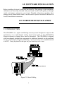
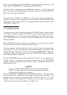
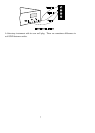
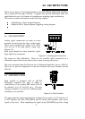
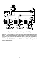
2.3 SIGNAL CABLE
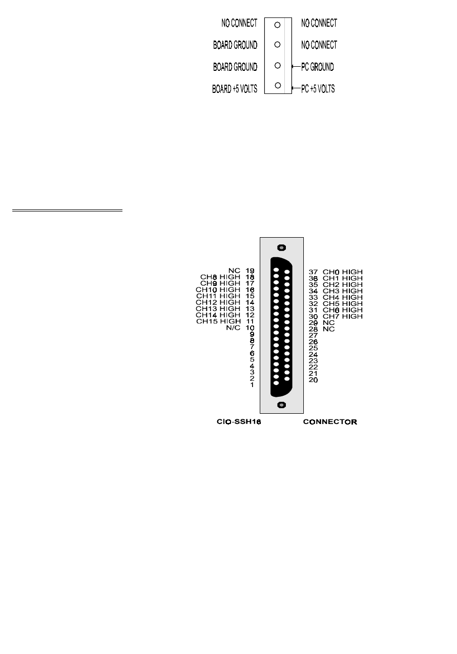
The CIO-SSH16 signal connector is nearly
a mirror of the CIO-DAS16 signal cable in
16 channel mode (Figure 1-2). There are
two 37D connectors on the CIO-SSH16
wired in parallel. The second, P19, permits
daisy chaining signals to other signal
conditioning or screw terminal boards.
Use any 37 conductor ribbon cable with
female D-37 connectors to connect a
CIO-SSH16 to a CIO-DAS16 or other
compatible analog input board. The cable
length should not exceed 10 feet.
Connect one end of the signal cable to the
analog input boards analog connector and
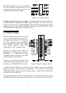
the other to the CIO-SSH16 P18 connector. Figure 1-2 Signal Connector Pin-out
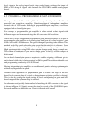
A shielded cable (C37FFS-#) is preferable if EMI or RMI is present with sufficient
energy to interfere with noise free measurements. The connection between the
CIO-SSH16 and the analog input board is single ended so signals on the cable have no
common mode noise rejection.
The signals labeled P13, P14, P15 & P16 (Figure 1-2) correspond to the four screw
terminal blocks where other signals coming from or going to your A/D board may be
3
P18 & P19
P13, +5V
P14, DA0
N/C
P14, GND
P14, IP1
P14, IP3
P13, OP1
P13, OP3
P13, OUT0
P16, DA1O
P16, S/H
P16, IP0
P16, IP2
P15, OP0
P15, OP2
P15, CLK1
P15, OUT2