


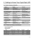
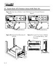

3E. Connecting the Optional Extended Battery
Plug the DC battery cable into the UPS module as shown in Figure 2a. The cable plug is keyed,
so make sure to align the plug properly to the receptacle. Do not force the cable on, nor attempt to
reverse the connection. To do so, will damage the equipment and void the warranty. Plug the AC
line cord into an AC line receptacle. See Figure 3f.
3F. Disconnecting the UPS & Battery to Take Out of Service
Turn off the UPS module by depressing the “Off” red button if the “inverter on” or "utility power
present" (bottom LED) is lit. Unplug the AC line cord for the battery module. Unplug the DC battery
cord. For extended batteries unplug AC line cord and DC battery cord.
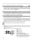
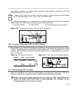
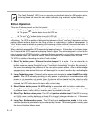
3G. Connecting to the Communication Ports
If you plan to utilize Solution-Pac HID ("human interface device" protocol), read the Solution-Pac HID
manual on the Solution-Pac CD for a full description of its features.
To connect to your computer, you will need the RS232 serial port or a USB (Universal Serial Bus)
port. The connection will be made between your computer’s serial or USB port and the serial or
USB port on the rear of the UPS module as shown in Figure 3d. Cables are supplied for this purpose.
A slide switch is provided for either RS232 or USB communication. The slide switch (shown in
Figure 3d)
is preset for RS232. Push the switch down for USB communication.
If communication does not operate, check the position of the slide switch.
The RS232 port also contains two low voltage (24 VDC)/low current (5MA) contact closures. See
Figure 3d
below. To use these an optional cable is available. These can be used by AS/400
computers or for special uses.
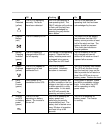
Figure 3a. RS232, Contact Closures and Remote Shutdown
1. Open
2. RTXD transmit (TX)
3. RRXD receive (RX)
4. OPEN
5. LOGIC RETURN (OV)
6. PNP (plug and play, do not use)
7. ALARM - Contact closure through a transistor
from pin 7 to pin 5 when "low battery".
8. RPO - A logic high will activate an output shutdown.
9. INVO - Contact closure through a transistor from
pin 9 to pin 5 when the unit is on Inverter.
3—2
5
9
4
3
2
1
8
7
6
OV
PNP
OV
RX
+8 to
+15VDC
TX
OV