


34008030EN/AA - Page 5
Contents
1. Presentation
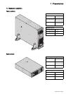
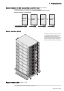
1.1 Standard positions ...................................................................................................................... 7
Tower position................................................................................................................................ 7
Rack position ................................................................................................................................. 7
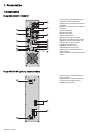
1.2 Rear panels................................................................................................................................... 8
Pulsar MX 4000 RT / 5000 RT....................................................................................................... 8
Pulsar MX EXB RT (optional battery module)................................................................................ 8
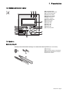
1.3 Display and control panel ........................................................................................................... 9
1.4 Options ......................................................................................................................................... 9
Rack mounting kit .......................................................................................................................... 9
ModularEasy MX.......................................................................................................................... 10
Battery extensions for UPS backup times up to 80 minutes.........................................................11
Battery Integration System ...........................................................................................................11
Battery extension cable ................................................................................................................11
2. Installation
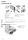
2.1 Unpacking and contents check ................................................................................................ 12
2.2 Internal batteries connection (Battery start-up)........................................................................ 12
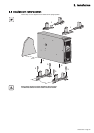
2.3 Installation in tower position .................................................................................................... 13
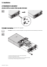
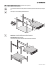
2.4 Installation in rack position ...................................................................................................... 14
Adjustment of the orientation of the logo and control panel......................................................... 14
UPS module rack mounting ......................................................................................................... 14
UPS or battery module rack mounting......................................................................................... 15
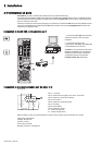
2.5 Communication ports................................................................................................................ 16
Connection to the RS232 communication port ............................................................................ 16
Connection to the communication port by relays ......................................................................... 16
Remote Power Off communication port ....................................................................................... 17
Installation of communication cards.............................................................................................17
2.6 Required protective devices and cable cross-sections......................................................... 18
Recommended upstream protection............................................................................................ 18
Recommended downstream protection ....................................................................................... 18
Required cable cross-sections..................................................................................................... 18
2.7 Connection of input/output power cables to UPS terminals ................................................. 19
2.8 Connection of IEC cables to output receptacles .................................................................... 20
3. Operation
3.1 Initial start-up ............................................................................................................................. 21
3.2 Final start-up sequence............................................................................................................. 21
3.3 Operating modes ....................................................................................................................... 22
3.4 Operation on battery power...................................................................................................... 23
3.5 Return on Normal AC source.................................................................................................... 23
3.6 UPS shutdown............................................................................................................................ 24
4. Access to measurements and personalisation data
4.1 Display organisation.................................................................................................................. 25
4.2 Access to measurements.......................................................................................................... 25
4.3 Access to UPS set-up and maintenance using the control panel......................................... 25
4.4 UPS set-up.................................................................................................................................. 26
4.5 Maintenance ............................................................................................................................... 27
4.6 Personalisation using external software ................................................................................. 27