


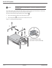

2.6 Remote Emergency Power Off (REPO) Communication Port
The end user is responsible for the installation of a Remote Emergency Power Off function. Installation must be
carried out in compliance with local code regulations.
To shutdown the entire system completely in case of emergency:
◗ Disconnect the AC input to the Power Module by opening up the upstream circuit breaker connecting the
utility power to the Power Module.
◗ Turn off the circuit breaker of the Battery Module connecting to the Power Module.
◗ Turn off the circuit breaker of the subsequent Battery Modules, if applicable.
All these steps above should be performed via a single device.
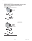
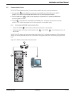
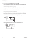
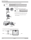
To simplify the last two steps, the Power Module provides an RJ-11, six contact connector on the back panel, called
Remote Emergency Power Off (REPO) port. Upon applying a voltage source (5-27VDC, 10mA max.) to pins 2, 4 of
this port, the Power Module will send a signal to trip off the shunt trip on each circuit breaker of all Battery Modules
via the battery detection cable simultaneously. Refer to the diagram below for details.
Figure 2-10a: Activation of Remote Emergency Power Off function using a contact normally open switch.
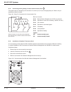
Figure 2-10b: Activation of Remote Emergency Power Off using a contact normally closed switch.
3
EX 5/7/11RT Systems
Installation2 — 12 86-86000-00 B00
5432
1
6
5VDC to 27VDC
10mA (max.)
RJ 11
+
_
Connections provided by user.
3
5432
1
6
RJ 11
+
_
Connections provided by user.
5VDC to 27VDC
10mA (max.)
3