


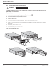
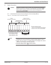
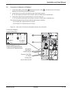


Proceed as follows:
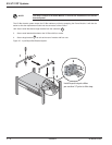
1. For normal AC input, make connections to L1, L2 and terminals only. No connections are required for
Bypass AC input. Make connections to , L5, L6 terminals for output.
CAUTION: Always connect the earth ground wire first.
Jumper must be between L1 and L3. System is factory configured for 208VAC
output.
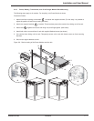
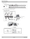
2. Attach I/O Box to the Power Module with three screws.
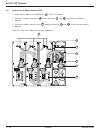
Figure 2-12: Normal AC Input and Output Cables installation.
EX 5/7/11RT Systems
Installation2 — 14 86-86000-00 B00
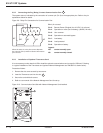
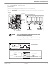
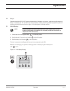
Card Settings
RS232 Download
66074
UPS
data
Reset
100 10
1 2
ON
ETHERNET
IP=
MAC=00E0D8FF855E
1
2
OF
F
O
O
F
F
O
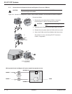
Output to Load
or
Transformer Module
(if applicable)
AC INPUT
UPSTREAM
CIRCUIT
BREAKER
(NOT SUPPLIED)
To Load or
Transformer Module
(if applicable)
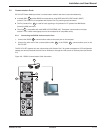
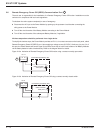
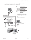
Normal AC
Simplified Connection Diagram
Normal AC Input
Output
L6 L5 L2 L1 L1 L4 L3
Jumper
Output
200/208/220/230/240Vac
Normal AC source
200/208/220/230/240Vac
Bypass AC source
200/208/220/230/240Vac
To Load
208VAC
From Utility
208 VAC
Power Module I/O Box
Bypass AC