


Installation and User Manual
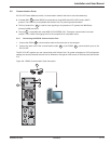
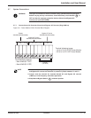
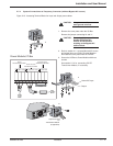
2.7.4 System Connections as Frequency Converter (without Bypass AC source)
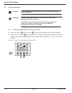
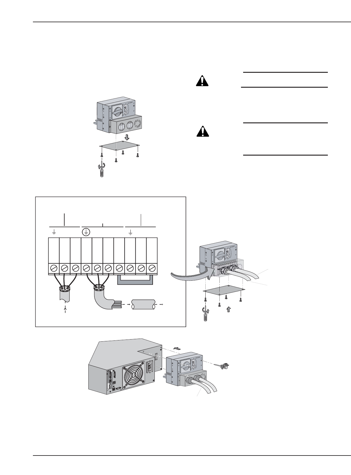
Figure 2-15: Accessing Terminal Blocks for Input and Output power cables.
Installation 2 — 1786-86000-00 B00
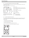
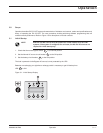
Card Settings
RS232 Download
66074
UPS
data
Reset
100 10
1 2
ON
ETHERNET
IP=
MAC=00E0D8FF855E
1
2
O
F
F
O
OF
F
O
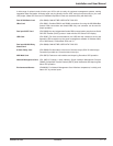
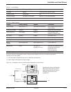
Output to Load
or
Transformer Module
(if applicable)
Normal AC Input
Output
L6 L5 L2 L1 L1 L4 L3
Jumper
Output
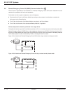
200/208/220/230/240Vac
Normal AC source
200/208/220/230/240Vac
Bypass AC source
200/208/220/230/240Vac
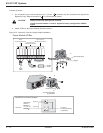
OUTPUT
To Load
208VAC
INPUT
From Utility
208 VAC
Power Module I/O Box
1
OF
F
O
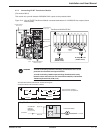
CAUTION: Always connect the
earth ground wire first.
1. Remove the cover plate under the I/O Box.
Remove the jumper connecting L3 and L1.
CAUTION: Removing the jumper will
disable the Bypass AC
source. Do not connect
anything to the Bypass AC
terminal block.
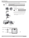
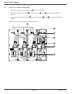
2. Refer to section 2.7.1 to install Normal AC source
and output wires per I/O Box Terminal diagram.
Re-install the cover plate under the I/O Box.
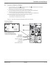
3. Secure the I/O Box to Power Module with three
screws.
See section 2.7.2 for connecting EX RT
Transformer Module, if necessary.