


Installation and User Manual
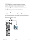
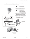
2.7 System Connections
WARNING This type of connections must be carried out by qualified electrical personnel.
Before carrying out any connections, check that battery circuit breaker is
OFF and that the upstream protection devices (Normal and Bypass AC
sources) are open (OFF/OPEN).
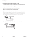
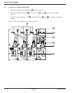
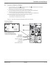
2.7.1 Connections with Common Normal and Bypass AC Sources (Single Mains)
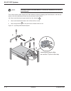
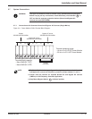
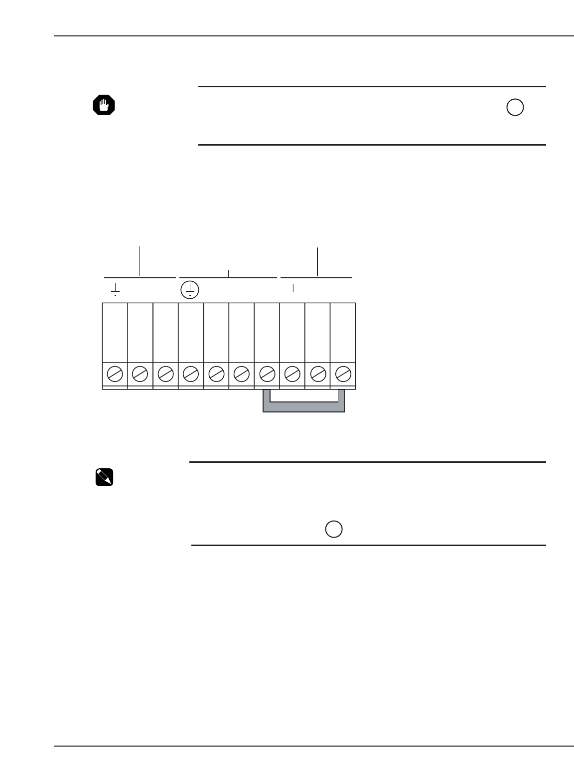
Figure 2-11: Power Module I/O Box Terminal Block Diagram.
NOTE ◗ The Power Module is factory configured for single input, whereas both Normal AC
and Bypass AC sources are identical, by means of jumper between L1 and L3.
◗ Jumper must be removed for separate Normal AC and Bypass AC sources
(2 Mains) or with Frequency Converter application.
◗ Keep Manual Bypass Switch at Normal position.
7
14
Installation 2 — 1386-86000-00 B00
L6 L5 L2 L1 L1 L4 L3
Jumper
(see note)
Output
200/208/220/230/240Vac
Normal AC source
200/208/220/230/240Vac
Bypass AC source
200/208/220/230/240Vac
Terminal block capacity:
- Max. 4AWG (EX 11RT)
- Max. 6AWG (EX 5/7RT)
Terminal tightening torque:
– 18 lb-in. for EX 5/7RT Power Module
– 35 lb-in. for EX 11RT Power Module