


www.apc.com / www.mgeups.com
THE UNINTERRUPTIBLE POWER PROVIDER
Network Shutdown Module V3 – User Manual - APC # 990-3630 (MGE # 34 003 934 XU / AB) Page 46/66
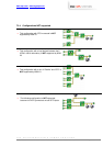
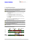
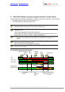
7.7 Multi UPS shutdown sequence (example with Static Transfer Switch)
Typical example of the backup time provided by 2 UPSs in redundancy through Static Transfer Switch.
ω The Output load level of the first UPS is less than 50 %.
ω The Output load level of the second UPS is 0 %.
1
As soon as they detect the loss of AC power, the Mgt. Cards notify the Network
Shutdown Modules that the system is running on battery power.
2
The Network Shutdown Modules continuously compute the “minimum number of
necessary UPSs”.
In this case we suppose that the minimal number is 1.
When the first UPS stops its output, the Static Transfer Switch balances the load on the
second UPS. Then we are in a typical « single UPS sequence »
3
ω The Mgt. Card launches the shutdown procedure for UPS 2.
ω As a result, each Network Shutdown Module proceeds with the shutdown of its
system.
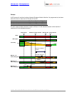
4
Once all the computers have been shut down, the UPS shuts off (interrupts the supply of
power to the loads) to protect the battery.
Note: This function is not authorized on some UPSs.
5
Once the utility is restored, the UPS restarts all computers (if the shutting off the UPS
output function available).
The diagrams below present the sequence.
Load
powered by
UPS2
Shutdown
criteria on
UPS2
System Shutdown
Duration
Utility Failure
Utility
UPS1 Output
UPS2 Output
Shutdown Mod
powered by STS
Utility Restored
1
2
3 4 5
6
UPS1
Shutoff
UPS 2
Shutoff
Shutdown
criteria on
UPS1
Load powered
by UPS1
Load
unpowered
Load powered
by UPS1