9
691 Wiring Instructions
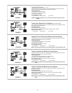
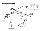
(Refer to diagrams on pages 14 & 15)
The 691 System is designed for use on vehicles with a
12 volt DC, negative ground system. References to
"ground" in this literature refer to vehicle chassis ground
which is connected to the negative (-) battery terminal.
References to "hot" or "positive" refer to connection to the
positive (+) terminal of the 12 volt DC battery.
Optional extension harness (32-820-022, page 19) is avail-
able from MICO, Incorporated when the control module is
not mounted directly to the power unit. The supplied wire
harness has been designed with sufficient wire length to
complete most installations. If additional wire is necessary,
be sure to use the proper gauge.
When making wire connections, soldering and sealing with
adhesive lined heat shrink is the recommended method.
All wires that are not used must be sealed and insulated to
keep from shorting to each other or ground.
Connecting External Inputs
Activating the 691 System by use of the user interface
rocker switch is not always convenient. External inputs can
activate the 691 System through the use of external
switches, dash mounted switches or relays. This provides
flexibility for manual operation by the user or allows other
circuits to activate the brakes.
External Inputs
There are three external inputs available. The 691 is
activated upon receiving a signal at any of the inputs and
does not deactivate until all input signals have been
removed.
Two of the external inputs are activated by a positive sig
-
nal (+12 VDC) and the third is activated by a negative
(ground) signal.
The negative input is accessed from the gray wire in the
main 691 Wire Harness.
The two positive inputs are:
1. The green wire in the user interface cable.
2. The brown wire in the main 691 Wire Harness.
NOTE: These inputs are connected together
internally, so if one is receiving a positive sig-
nal, the other will also have a positive signal
present. This is commonly used to provide an
external signal (to the brown wire) when the
switch on the 691 User Interface is activated.
To prevent unintentional activation of the 691 System,
insulate and seal any of the unused wires.
Using the Brown Wire as an External Output
When activating the 691 System with the user interface,
the brown wire can be used to signal other circuits. It will
provide a positive signal up to 1 amp of power to lights,
relays, etc. If this current limit is exceeded, the output or
control module may operate erratically or not at all.
*NOTE: The brown wire will not provide an output
when the 691 System is activated by the external input
of the gray wire. This is an inherent design to provide
protection from improper wiring.
Connecting the Vehicle Horn
The yellow 691 harness wire must be connected to a horn
or other suitable warning device for your application. The
yellow wire sends a ground signal to sound the horn when
necessary.
1. On most vehicles the best way to connect this wire
without adding a relay is to find the horn wire from
the horn switch in the steering wheel. This switch
typically grounds this wire to sound the horn, splic-
ing in the yellow wire at this point is all that is
necessary.
2. If splicing into the horn switch wire is not convenient,
add a relay that is switched by the ground signal from
the yellow wire and that connects the appropriate
signal directly to the horn itself.
The yellow wire will provide a ground of up to 1
amp to drive a warning device. If this current limit is
exceeded or if the yellow wire is connected improper-
ly, the warning device or control module may operate
erratically or not at all. Be sure to check for proper
operation of the horn circuit on a regular basis. See
page 11, "HORN WARNING CIRCUIT TEST".
Connecting Power for the Control Module
1. Connect the black wire directly to battery negative or
equivalent ground. This wire carries the full current of
the 691 System and must have a good ground. If
additional wire is necessary for this connection it must
be a minimum of 14 gauge wire.
2. Connect the red wire to a 30 amp fuse which is
connected directly to battery positive. This wire also
carries full 691 System current. Do not connect this
through any auxiliary wiring. Do not use a slow blow
fuse or circuit breaker.
Power is supplied to the 691 Control Module at all times.
To prevent unintended actuation of the 691 System, be
sure the "lock" - "release" switch (if applicable) is in the
"release" position.
Do not operate the 691 Power Unit without first filling the
power unit reservoir with proper fluid.
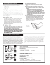
WIRING
NOTE
All positive connections to the battery must be made
through a high quality, properly rated fuse. Do not use a
slow blow fuse or circuit breaker.
If the gray wire is allowed to short to ground, the vehi
-
cle brakes will apply.


