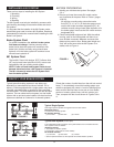
CAUTION Label
Pressure
Switches
6
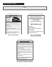
Several self adhesive labels are supplied with each 691
Brake Lock. Determine which labels are used in your
application and affix in the vehicle cab in view of the
operator. See page 1.
Actuator
1. Repeat the mounting procedures for each actuator
used in your system.
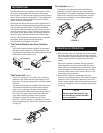
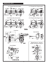
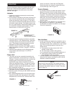
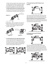
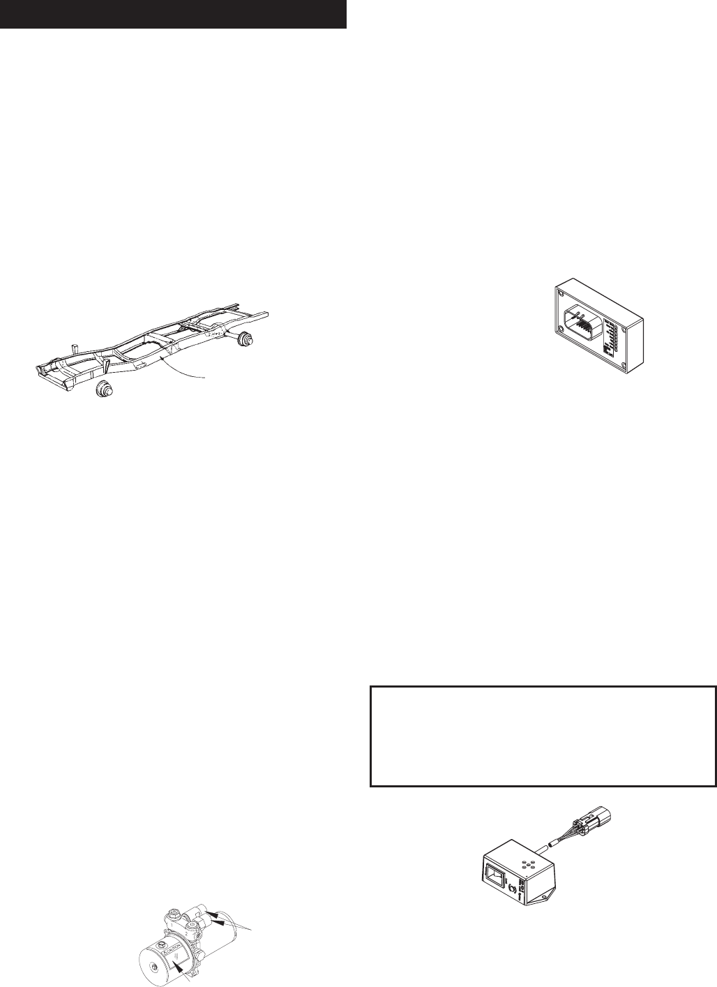
2. Find a location, preferably on the frame rail away from
heat, where the actuator(s) will mount allowing easy
access to brake lines, refer to Figure 12. The actua-
tor(s) must be mounted horizontally below the level of
the vehicle master cylinder. The bleeder screws must
be in an upright position. Relocate the bleeder screws
as necessary to maintain upright position. Torque
bleeder screws 17.6-20.3 N-m (13-15 lb-ft).
3. Using the actuator mounting brackets as a template,
mark and drill four 11/32" diameter holes. Fabricated
mounting brackets can be used to mount the actua-
tor(s). The strength of fabricated brackets must be
adequate to prevent flexing of brake lines.
4. Install the actuator using four 5/16-18UNC, grade 5,
bolts, lock washers, and nuts. Torque 27.1-33.9 N-m
(20-25 lb-ft).
5. Install the brass adapters from the fitting package
in the actuator ports and torque 7.9-10.2 N-m
(70-90 lb-in).
Power Unit
1. The power unit can be mounted horizontally in the
engine compartment, on the frame rail, or in the cab.
However, it must be protected from dirt, moisture and
possible impact. Easy access to the reservoir
breather/filler plug must be maintained to allow for
filling and checking fluid level. The reservoir breather
plug must be kept in an upright position. If this is not
possible a remote reservoir can be installed, refer to
691 accessories on page 19.
2. Mark and drill two 7/16" diameter holes 2 5/16" apart.
Fabricated mounting brackets can be used.
3. Mount the power unit using two 3/8-16UNC bolts and
lock washers.
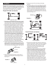
4. 691 models designated (HO) must use mineral base
hydraulic oil in the power unit reservoir. 691 models
designated (SF) must use DOT 5 silicone fluid in the
power unit reservoir. Check the CAUTION label
around the power unit reservoir breather/filler plug
to verify fluid type, refer to Figure 13.
Control Module
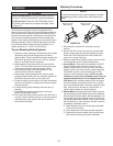
1. A mounting bracket is provided with the 691 Control
Module to mount the control module directly to the
691 Power Unit. See power unit dimensional drawing
on page 5. The control module can be mounted on top
of the power unit as shown, as well as mounted to
either side. The control module can also be mounted
to position the harness connection in the opposite
direction shown.
2. When the 691 Control Module is not mounted to the
691 Power Unit, an optional 11' wire harness
(32-820-022) is available from MICO, Inc. See page
19 for 691 Accessories.
User Interface
1. A dash mounted user interface is provided for use by
the operator in the cab. The user interface includes a
manually activated switch, audible alarm, and "locked"
lamp. Find a mounting location in the cab of the
vehicle where:
A. The operator has easy access to the "lock" -
"release" rocker switch.
B. The "lock" lamp is visible to the operator.
C. It is protected from having something spilled on it.
D. There is easy routing of wires from the 691
Control Module to the user interface.
2. The user interface is not necessary for applications
where the 691 System is activated by other manual
switches or electrical interlocks.
FIGURE 12
FIGURE 13
MOUNTING
RECOMMENDED ACTUATOR
MOUNTING LOCATION -
INSIDE OR OUTSIDE FRAME RAIL
FIGURE 14
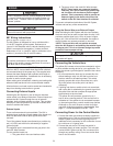
NOTE
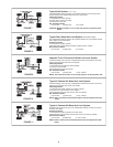
When the 691 User Interface is not installed with this
system, another visual identifier must be used to inform
the operator that the 691 System is "locked". See sche
-
matic on page 14.
FIGURE 15


