


2
Vehicles today have two separate brake systems. One is
the service brake system and the other is the parking
brake system. The service brake system is used to slow or
stop a vehicle during normal operation. The parking brake
system is usually cable operated and used to hold the
vehicle stationary while parked.
Experience has shown that some vehicle applications re
-
quire more brake holding capacity than provided by prop
-
erly maintained parking brakes. The MICO 691 Brake
Lock System uses the vehicle service brakes to supple
-
ment the parking brake. The 691 System provides pres
-
sure to the service brake system in the same manner as
when the vehicle operator presses on the brake pedal.
The 691 also provides external inputs which can activate
the system without direct operator interjection.
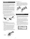
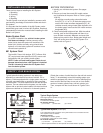
The 691 Brake Lock System consists of:
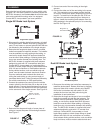
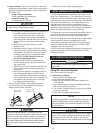
The Control Module and User Interface
(Figure 1)
The control module controls operation of the system
through the user interface or remote activation. The
user interface incorporates a manually activated switch,
audible alarm, and "locked" lamp.
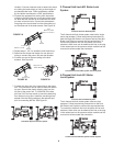
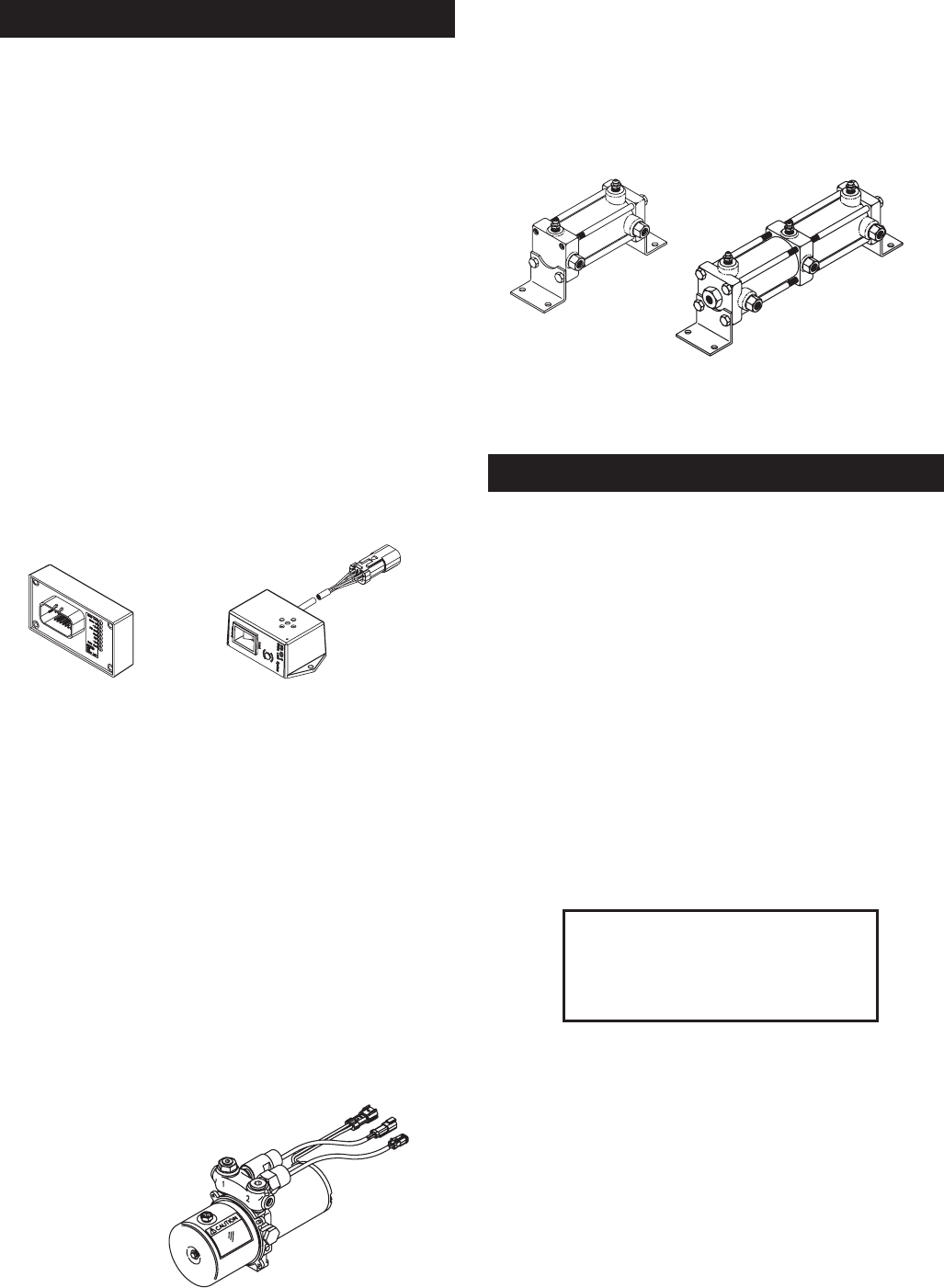
The Power Unit (Figure 2)
The power unit uses a 12 volt DC pump to produce
pressure in the vehicle service brake system to lock
the brakes. The pump reverses flow to release locking
pressure.
Two pressure switches are located on the power unit.
The pressure switches sense the pressure that the
power unit is producing. The high pressure switch
starts and stops the pump while pressurizing the sys-
tem. The low pressure switch starts and stops the
pump while releasing pressure from the system.
Although the power unit contains a built in fluid
reservoir, a remote reservoir is available as an option
for special applications. Refer to 691 Accessories chart
on page 19.
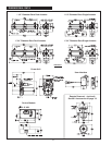
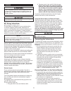
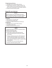
The Actuator (Figure 3)
The actuator is a mechanical device that links the
hydraulics of the 691 System to the vehicle service
brake system. The actuator separates the 691 System
fluid from the vehicle service brake system. Various
actuators are available for use in different types of
service brake systems.
FIGURE 1
FIGURE 3
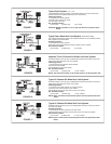
1. When the 691 System is activated, the control module
starts the power unit pumping fluid into the actuator(s).
As the actuator(s) become pressurized they isolate the
vehicle master cylinder and pressurize the service
brakes.
When lock pressure is reached, the high-pressure
switch signals the control module to stop the pump.
While the pump is stopped, locking pressure is held in
the brake system. If locking pressure drops, the high
pressure switch signals for the power unit to turn "on"
and restore locking pressure.
2. When the 691 System is deactivated, the pump
reverses and releases pressure. The actuator releases
pressure from the brakes and opens the ports to the
vehicle master cylinder. When locked pressure returns
to zero psi a signal from the low-pressure switch stops
the pump.
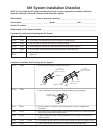
INTRODUCTION
PRINCIPLE OF OPERATION
NOTE
Brake System fluid and 691 Sys
-
tem fluid always remain isolated
from one another.
FIGURE 2
Control Module
User Interface