3
There are four steps to installing the 691 System.
1. Mounting
2. Plumbing
3. Wiring
4. Bleeding
The 691 System must only be installed by someone with
good working knowledge of automotive brake and electri
-
cal systems.
It is important that the installer of the 691 System under
-
stands fluid types used in various 691 Systems. Read and
understand this instruction manual before installing the 691
Brake Lock System.
Brake System Fluid
For all 691 installations the vehicle’s brake system
fluid does not change. Vehicles currently using
brake fluid in the brake system will continue to use
brake fluid. Vehicles currently using mineral base
hydraulic oil in the brake system will continue to use
mineral base hydraulic oil.
691 System Fluid
The two 691 Power Unit designs, DOT 5 silicone fluid
(SF) and mineral base hydraulic oil (HO), assure seal
compatibility with your existing brake system.
NOTE: Power unit and brake system fluids do not
become intermixed when a 691 System is installed.
The 691 Actuator(s) isolate the 691 System fluid
from the brake system.
BEFORE PROCEEDING:
1. Identify your vehicle brake system. See pages
3&4.
2. Be sure you have the correct 691 model number
and it contains all the parts. Refer to Table 1 (pages
19 & 20).
All vehicles currently using automotive brake
fluid (DOT 3, 4, 5 or 5.1) in the brake system must
use the 691 model numbers designated (SF). All
vehicles currently using mineral base hydraulic oil in
the brake system must use the 691 model numbers
designated (HO).
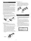
3. Check brake pedal height and feel. With the vehicle
running, push on the brake pedal until there is no
more forward movement. Measure and record the
distance from pedal to floor. Brake pedal height and
"feel" will be the same after the 691 System is in-
stalled, refer to Figure 4.
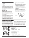
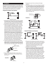
FIGURE 4
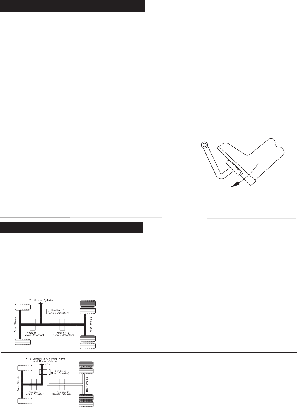
Typical hydraulic braking systems in use today vary
depending on manufacturer and size of vehicle. For in
-
stance, a vehicle equipped with a single system may have
a firewall mounted booster or possibly a frame mounted
remote booster. The same holds true for the dual and split
systems. The rear wheel anti-lock system is a dual brake
system with an anti-lock valve installed. All-wheel anti-lock
systems are defined as 3-channel or 4-channel systems
(Check the number of outlet lines from the anti-lock control
valve). To be absolutely sure which braking system your
vehicle is equipped with, check it. Look for identifying fea
-
tures such as dual flex lines at rear axle or front wheels,
number of master cylinder lines, anti-lock valve(s), etc.
Then, compare with the circuits shown in Figures 5 thru
11.
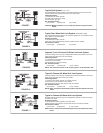
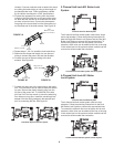
Typical Single System
One single hydraulic system serving both front and rear brakes.
Identifying Feature:
1.One line from master cylinder.
691 Actuator Position:
(1) Front axle (2) Rear axle (3) 4-wheel
Typical Dual System (Vertical Split)
Two independent braking systems. One system leads to the front brakes and the
other system to the rear brakes.
Identifying Feature:
1.Two lines from master cylinder.
2.Combination valve (used on some models).
691 Actuator Position:
(1) Front axle (2) Rear axle* (3) 4-wheel
* Some imported vehicles use two separate air boosted master cylinders.
FIGURE 5
FIGURE 6
INSTALLING A 691 SYSTEM
IDENTIFY YOUR BRAKE SYSTEM


