7
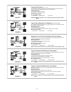
Determine the type of brake system on your vehicle, refer
to pages3&4.Allbrake systems in use today require the
MICO 691 Actuator(s) be installed after the anti-lock brake
valve and combination warning valve if so equipped.
Contact MICO, Incorporated if you have questions.
Single 691 Brake Lock System
1. Disconnect the existing brake line necessary to install
the single actuator. Reduce fluid loss by plugging the
ports. Do not loosen or remove hydraulic lines that are
not effected by the installation of the single actuator.
2. Determine the length and shape of new or modified
brake lines needed to install the actuator. The installer
must be qualified to modify existing brake tubing, or
new factory double flared SAE approved brake line
must be used. When adding or replacing brake lines,
do not use smaller diameter than existing lines. The
MICO 691 Actuator is supplied with brass adapters
designed to mate with 1/4" inverted flare tube nuts.
Contact MICO, Incorporated or a local brake fitting
supplier to obtain proper fittings to install different size
lines. All new connections or modifications between
flexing vehicle sections, such as vehicle body and
frame, must be made to absorb shock and vibration.
Common methods used to absorb this shock are
coiling the brake tubing or using a short length of
purchased brake hose. Follow procedures outlined by
the vehicle manufacturer or SAE specifications.
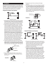
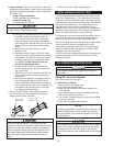
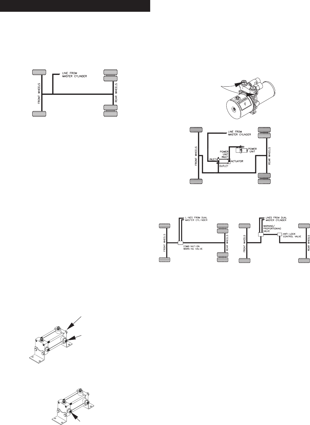
3. Connect the upstream line coming from the vehicle
master cylinder to the fluid inlet port on the end of the
single actuator. Connect the downstream line going to
either the front or rear brakes from the side outlet port
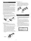
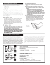
on the same end of the single actuator. See Figure 16.
4. Determine the shape and length of a new piece of
tubing to connect the power unit and single actuator.
See Figure 17.
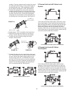
5. Connect one end of the new tubing to the single
actuator.
6. Connect the other end of the new tubing to the power
unit. This connection can be made to either the side
or top port. Remove the plastic shipping plug from the
top port. To install line in the side port use 3/16" hex
key wrench to move the steel plug from side port to
top port. Install the remaining brass adapter from the
fitting package in the selected port prior to connecting
the line. See Figure 18.
Dual 691 Brake Lock System
1. Disconnect the existing rear brake lines necessary to
install the dual actuator. Reduce fluid loss by plugging
the ports. Note which master cylinder port supplies
fluid to the front brakes and rear brakes. Do not
reverse the front and rear fluid paths during the
installation of new brake lines.
2. Determine the length and shape of new or modified
brake lines needed to install the dual actuator. The
installer must be qualified to modify existing brake
tubing, or new factory double flared SAE approved
brake line must be used. When adding or replacing
brake lines, do not use smaller diameter than existing
lines. The MICO 691 Actuator is supplied with brass
adapters designed to mate with 1/4" inverted flare
tube nuts. Contact MICO, Incorporated or a local
brake fitting supplier to obtain proper fittings to install
different size lines. All new connections or modifica-
tions between flexing vehicle sections, such as vehicle
body and frame, must be made to absorb shock and
Single Brake System
F
rom
Master Cylinder
(port not shown)
To Brakes
From
P
o
w
e
r
U
ni
t
FIGURE 16
FIGURE 17
PLUMBING
Single Brake System with 691 System
Plug One of
These Ports
FIGURE 18
Dual Brake Systems


