


UNO-3074 User Manual 18
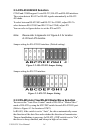
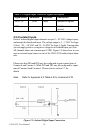
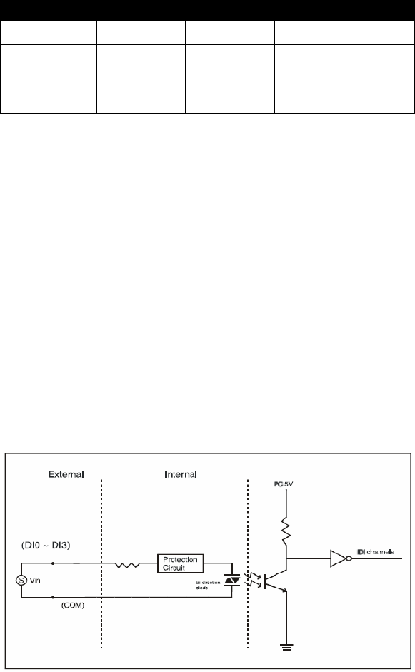
2.5.2
Isolated
Inputs
Each of isolated
digital input channels accepts 0
~ 50
VDC
voltage inputs,
and
accepts bi-directional
input. The voltage range is -3 ~ 3 VDC for logic
0 (low), -50 ~ -10 VDC and 10 ~ 50 VDC for logic 1 (high). It means that
you can apply
positive
or negative voltage to
an
isolated input
pin (Vin).
All
channels share one common
pin (COM). Figure
2.5 shows how to con-
nect an external
input
source to one
of
the UNO-3074 isolated input chan-
nels.
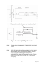
Please note
that DI0
and DI2
may be configured as
gate control pins of
Counter 0 and Counter 1;
While DI1
and DI3 may be configured as input
pins of Counter 0
and Counter 1. Please refer to section 2.7 for
details
Figure 2.5:
Isolated Digital
Input Connection
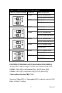
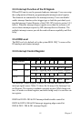
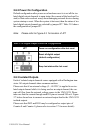
Table 2.4: Digital Input Connector Signal Description
Signal Name Reference Direction Description
DI <0...3> COM Input Isolated DI signals
COM - - DI, DO isolated
ground
Note: Refer to Appendix A.3 Table A.6 for command of DI