


27 Chapter 2
2.7.8
Counter Output Destination
Yo u
can
choose
the output destination of
counter
0
and counter 1 by setting
“Output
Destination control
bits”- CTR0OutSet
and CTR1OutSet.
2.7.9
Counter Interrupt Flag
The interrupt
flag
bit is
a flag indicating the status of
an
interrupt.
It is a
readable/writable bit. To find the status of the interrupt, you
have
to read
the bit
value; to
clear the interrupt, you
have
to write “1” to this bit.
This bit
must first be
cleared to service the next
coming interrupt.
Besides, you can
choose
if counter 0 or counter
1 generate interrupt signal by configuring
“CTR0IntSet” and “CTR1IntSet” control
bit.
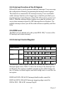
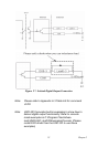
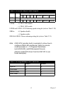
Table 2.14: Counter Gate Source Control Bit
CTR0GateSet 0 Gate source from “CTR0Gate” control bit (Default)
1 Gate source from digital input 0 (DI0) channel
CTR1GateSet 0 Gate source from “CTR1Gate” control bit (Default)
1 Gate source from digital input 2 (DI2) channel
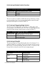
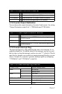
Table 2.15: Counter Output Destination Control Bit
CTR0OutSet 0 Output destination to “CTR0Out” status bit (Default)
1 Output destination to “CTR0Out” status bit and digital output
2 (DO2) channel
CTR1OutSet 0 Output destination to “CTR1Out” status bit. (Default)
1 Output destination to “CTR1Out” status bit and digital output
3 (DO3) channel
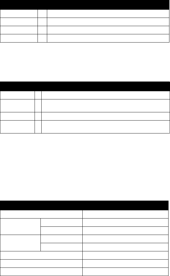
Table 2.16: Counter Interrupt Flag Control Bit
CTR0F, CTR1F Counter Interrupt Status
Read 0 No interrupt
1 Interrupt occur
Write 0 Don’t care
1 Clear interrupt
CTR0IntSet, CTR1IntSet Counter Interrupt Control
0 Disable (Default)
1 Enable