


UNO-3074 User Manual 30
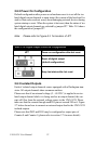
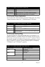
PWR =0, Power
fail
=1, Power
normal
P1 (24V) =0, Power
input 1
fail
=1, Power
input 1
normal
P2 (24V*) =0, Power
input 2
fail
=1, Power
input 2
normal
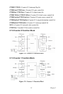
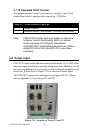
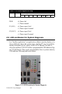
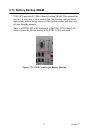
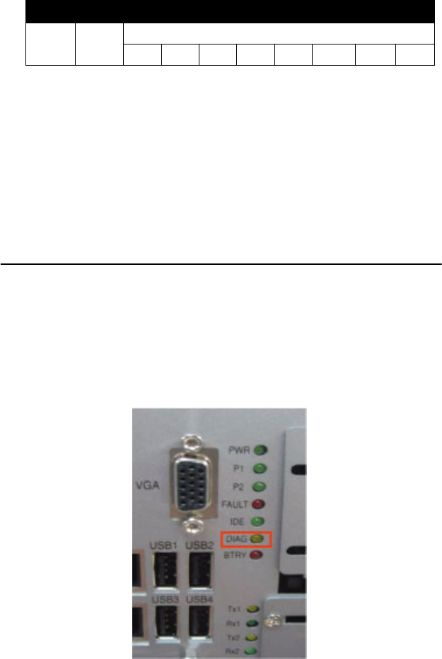
2.9 LED and Buzzer for System Diagnosis
In
a “headless application” (an
application
without a
monitor display), it is
always
difficult
to
know the system status. Another
PC
may be needed to
monitor a headless device's status via RS-232 or
Ethernet. In
order
to
solve this problem, UNO-3074 offers
a programmable LED
indicator (Fig-
ure 2.13) and buzzer.
They can be programmed
to show a
systems status by
LED indicator flickering
and buzzer
alarm.
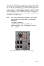
Figure 2.13:
LED Location for System Diagnosis
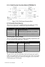
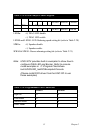
Table 2.18: Power Register Bit Map
218H R Power Register
PWR P2 P1