


UNO-3074 User Manual 24
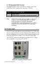
2.7 Onboard Isolated Counter/Timer
The UNO-3074
uses one 82C54 programmable timer/counter
chip that
includes
three independent 16-bit
down
counters: counter 0,
counter 1 and
counter 2.
Counter 0 and counter
1 are
for users, and counter 2 is specified
for
the
system and can’t be
used by user.
Each counter has
clock input,
gate
input and pulse output. They can be programmed to count from 2 up to
65535
or cascaded into one 32-bit
counter.
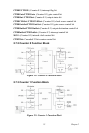
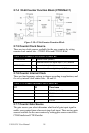
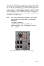
The UNO-3074 has two isolated counter input channels designated DI1
and DI3 with two isolated output channels designated DO2 and DO3.
Therefore,
you
can set
each counter of 82C54
as
counter function or timer
function.
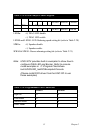
2.7.1
Counter/Timer Control
Register
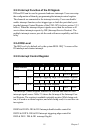
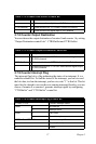
The Counter/Timer Control Register controls the
function and
status
of
each counter/timer signal
source. Table
2.11
shows
the bit map of the
Counter/Timer Control Register. The register is readable/writable register.
While being written, it
is used
as a control register;
and
while
being read,
it
is used as
a status
register.
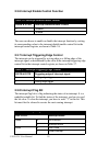
Table 2.11: Counter/Timer Control Register Bit Map
Base
Address
7 6 5 4 3 2 1 0
207H R/W Interrupt Flag/Clear Register
CTR1F CTR0F
208H R/W 82C54 Chip Counter0 Register
209H R/W 82C54 Chip Counter1 Register
20BH R/W 82C54 Chip Control Register
20CH R/W Counter0 Start Control / Output Status Register
CTR0
Out
CTR0
Gate
20DH R/W Counter1 Start Control / Output Status Register
CTR1
Out
CTR1
Gate
20EH R/W Counter0 Setting Register
CTR0
IntSet
CTR0
OutSet
CTR0
GateSet
CTR0
CLKSet
20FH R/W Counter1 Setting Register
CTR3
2Set
S1 S0 CTR1
IntSet
CTR1
OutSet
CTR1
GateSet
CTR1
CLKSet