


2408
f
& 2404
f
PROFIBUS Communications Handbook Troubleshooting
2408
f
and 2404
f
PROFIBUS Communications Handbook 6-1
CHAPTER 6 TROUBLESHOOTING
No Communications:
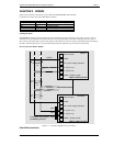
• Check the wiring carefully, paying particular attention to the continuity of the A and B connections to the Master. Ensure
that the correct terminals have been wired to.
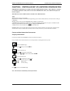
• Access the list in configuration level and check that the function ( ) is set to . If not, the controller is not
configured for PROFIBUS-DP.
• Check Node Address ( ) in the list is correct for the network configuration in use.
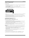
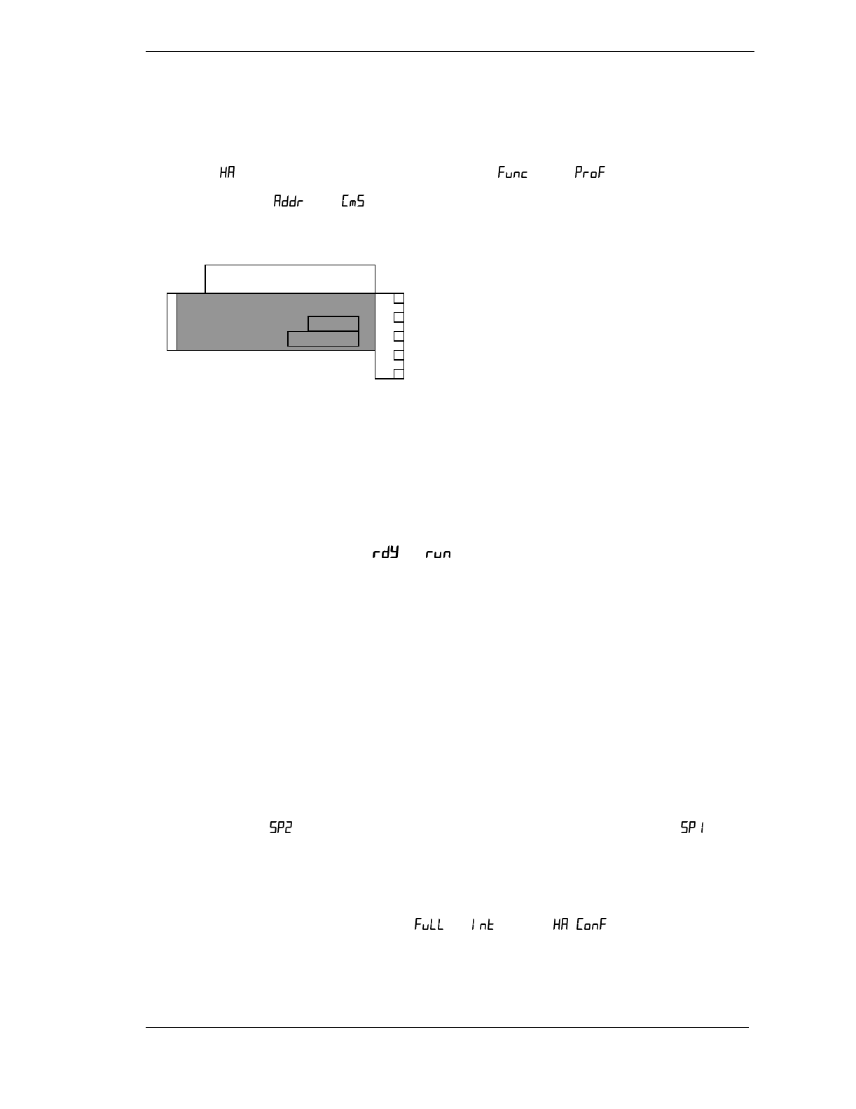
• Ensure that a PROFIBUS-DP Comms Module is installed in slot H of the 2404/8
f
. It can be identified by of the legend on
the plug-in module casing, and its distinctive shape:
• Ensure that the network is correctly configured and the configuration has been transmitted correctly to the PROFIBUS-DP
master.
• Verify the GSD file in use is correct by loading it into the GSD File Configuration. This will check the format.
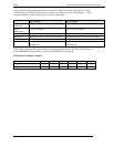
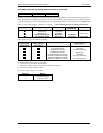
• Verify that the maximum line length for the baud rate in use is not exceeded (see table above). Note that the 2404/8
f
is
restricted to use at a maximum rate of 1.5 Mbaud.
• Ensure that the last device (not necessarily a 2404/8
f
) in the network segment is correctly terminated (see wiring diagram).
• Ensure that no devices other than those at the end of a network segment have termination networks fitted.
• If possible, replace suspect device with a duplicate and retest.
Intermittent Failure to Communicate.
Intermittent Flickering of Status From ‘
’ to ‘
’.
Diagnostic Status Changing but no Alarms Present in the Controller.
• Verify wiring, paying particular attention to screening.
• The I/O data length may be too long. Some PROFIBUS-DP Master implementations can accept no more than 32 input
and 32 output words per slave device. Verify by reference to documentation of the Master.
• Verify that the maximum line length for the baud rate in use is not exceeded (see cable specifications). Note that the
2404/8
f
is restricted to use at a maximum rate of 1.5 Mbaud.
• Ensure that the last device (not necessarily a 2404/8
f
) in the network segment is correctly terminated (see wiring diagram).
• Ensure that no devices other than those at the end of a network segment have termination resistors fitted.
• Verify operation with a duplicate device if possible.
Setpoint, Output Power, Auto/Manual etc ‘jammed’ to one setting and cannot be altered using controller
front panel.
• PROFIBUS-DP writes all ‘output’ data continuously, so that if Output Power, Setpoint, or Auto/Manual status are
included in the output data, their settings, as stored in the master data registers, will override any setting entered using the
front panel of the controller. To avoid this, here are some suggestions for possible techniques.
• Use ‘Demand Data’ to write parameter values only when changes are required
• (Setpoints only) Use as a ‘manual’ setpoint, selectable locally using a digital input or key switch, and as a
‘PROFIBUS-DP remote’.
• Note that when the network fails and the instrument goes off-line to PROFIBUS-DP, the front panel will regain full
control, so that the controller may be used as a local ‘island’ of control.
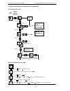
Data format or parameter data seems incorrect
• Verify that the data format is correctly configured (‘ ’, or ‘ ’), from the list in the controller.
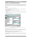
Verify that the GSD file is correct for the given application by loading it into the GSD file configurator program.
EUROTHERM CONTROLS
SUB24/PB PROFIBUS
AH026222 U002
Iss No.
DATE