


2408
f
& 2404
f
PROFIBUS Communications Handbook Controller Set Up & Network Configuration
2408
f
and 2404
f
PROFIBUS Communications Handbook 4-1
CHAPTER 4 CONTROLLER SET UP & NETWORK CONFIGURATION
PROFIBUS-DP communications is available in Eurotherm 2408
f
and 2404
f
controllers. Other 2000 series controllers
(i.e. controllers without the
f
suffix) cannot be converted to PROFIBUS-DP comms, since a different microprocessor
board is required.
Main Differences between 2400
f
Controllers and Other Series 2000 Instruments.
2400
f
The 20 program variant is not available
EI Bisynch is not available. The Instrument Programming System software, IPSG, therefore, cannot be used for cloning or
configuration.
Module slot H can only be used for PROFIBUS-DP or Modbus communications.
A PROFIBUS-DP module fitted to 2400
f
may be configured to Modbus communications if required. A Modbus module
fitted to any other 2000 series instrument cannot be configured to PROFIBUS-DP.
A PDSIO master or slave module can only be fitted in module slot J.
PROFIBUS-DP may be used with either mains powered and 24V AC/DC controllers, and in all respects, other than those
described above, they are standard units and may be used in exactly the same way as other 2400 series controllers.
C
ONTROLLER
N
ODE
A
DDRESS
A
ND
C
ONFIGURATION
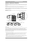
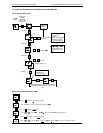
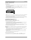
Assigning a Node Address
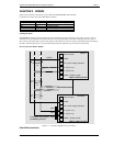
Connect the controller to the PROFIBUS network as described in Chapter 3.
Every controller on the network must have its own unique address to distinguish it from any other.
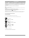
Press to return to the HOME display
Note: The baud rate is automatically selected by the master.
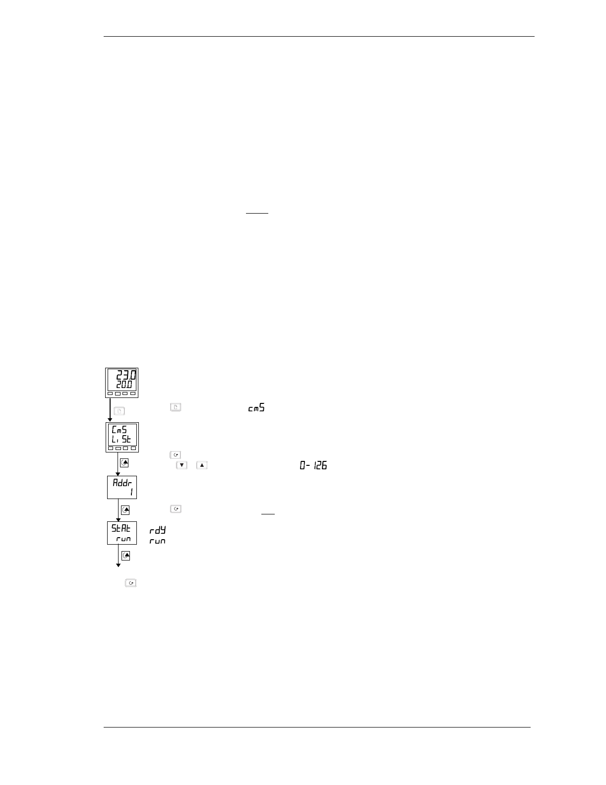
From the HOME display,
press
until you reach the list
From the Comms List
Press
to display the node address.
Press
or
to set the desired address.
From the Address List
Press
to display the Comms Status
This is a read-only diagnostic display
Ready to run
Comms running