Principles of Operation 2408
f
& 2404
f
PROFIBUS Communications Handbook
2-2 2408
f
and 2404
f
PROFIBUS Communications Handbook
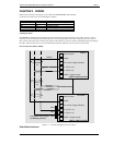
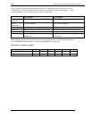
Typically no more than 32 bytes of input data and 32 bytes of output data are exchanged for each device during the data
exchange. Some PLC masters allow no more than this, although the PROFIBUS-DP standard provides the possibility of
transferring 236 bytes in each direction. The input and output data lengths for a given device are variable and it is possible to
have devices with only input data, only output data, or both.
The input and output data mixture used by a given slave device is defined by what is known as a GSD file. See Chapter 5 for
more details. For simple devices such as digital or analogue I/O blocks, this is fixed. However, since more complex devices
often have a much wider choice of possible values to send, it is usually possible to edit the GSD file to change the mapping of
device parameters onto Profibus inputs or outputs. This is the case with most Eurotherm implementations, which also allow
access to parameter data not in the GSD Input/Output data file. This is called Demand Data and is described further in
Chapter 7.
The GSD file is imported into the PROFIBUS Master Network Configuration software before the network is created.
NB: PROFIBUS Input Data = Values sent from a device to a master controller or PLC,
PROFIBUS Output Data = Values sent from a master controller or PLC to a device


