2408
f
& 2404
f
PROFIBUS Communications Handbook Tag Addresses
2408
f
and 2404
f
PROFIBUS Communications Handbook 8-5
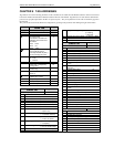
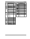
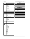
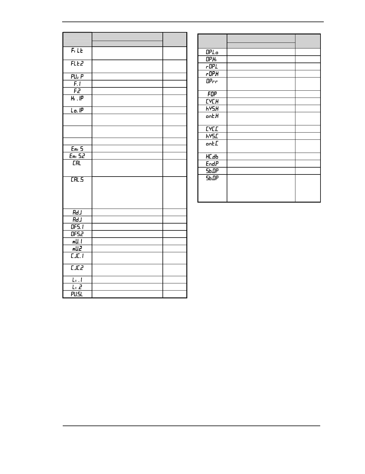
Controller
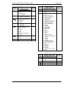
Input Tab
Tag
Display Parameter Description Address
Input 1 filter time constant
0: Off
101
Input 2 filter time constant
0: Off
103
Select input 1 or input 2 288
Derived input function factor 1 292
Derived input function factor 2 293
Switchover transition region
high
286
Switchover transition region low 287
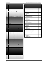
Potentiometer Calibration
Enable
310
Potentiometer Input Calibration
Node
311
Potentiometer Calibration Go 312
Emmisivity 38
Emmisivity input 2 104
User calibration enable
0: Factory
1: User
110
Selected calibration point
0: None
1: Input 1 low
2: Input 1 high
3: Input 2 low
4: Input 2 high
102
User calibration adjust input 1 146
User calibration adjust input 2 148
Input 1 calibration offset 141
Input 2 calibration offset 142
Input 1 measured value 202
Input 2 measured value 208
Input 1 cold junction temp.
reading
215
Input 2 cold junction temp.
reading
216
Input 1 linearised value 289
Input 2 linearised value 290
Currently selected setpoint 291
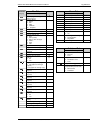
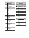
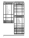
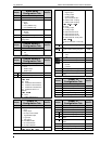
Controller
Output Tab
Tag
Display Parameter Description Address
Low power limit 31
High power limit 30
Remote low power limit 33
Remote high power limit 32
Output rate limit
0: Off
37
Forced output level 84
Heat cycle time 10
Heat hysteresis (on/off output) 86
Heat output minimum on time
0: Auto
45
Cool cycle time 20
Cool hysteresis (on/off output) 88
Cool output minimum on time
0: Auto
89
Heat/cool deadband (on/off op) 16
Power in end segment 64
Sensor break output power 34
On/Off Sensor Break Output
Power
0: -100%
1: 0%
2: 100%
40


