


Tag Addresses 2408
f
& 2404
f
PROFIBUS Communications Handbook
8-14 2408
f
& 2404
f
PROFIBUS Communications Handbook
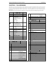
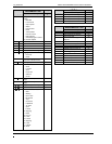
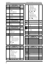
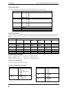
Program General Data
The offsets of each parameter within the program general data block is given by the next table:
Address Offset Parameter
0 HoldbackType
0: None
1: Low
2: High
3: Band
1 HoldbackValue
2 Ramp Units
0: Secs
1: Mins
2: Hours
3 Dwell Units
0: Secs
1: Mins
2: Hours
4 Program Cycles
5 Reserved
6 Reserved
7 Reserved
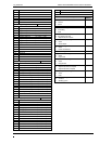
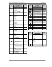
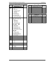
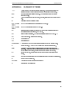
Program Segment Data
Program segment data is specified using 8 tag addresses, with the contents varying depending on the type of the segment. The
format per segment is detailed in the following table, which gives the offset from the start of a segment data block for each
item.
Address Offset Segment Types
STEP DWELL RAMP
RATE
RAMP
TIME TO
TARGET
CALL END
0 Segment Type Segment Type Segment Type Segment Type Segment Type Segment Type
1 Target
Setpoint
Target
Setpoint
Target
Setpoint
2 Duration Rate Duration
3 Program
Number
End Type
4 Logic O/P’s Logic O/P’s Logic O/P’s Logic O/P’s Call Cycles Logic O/P’s
5
6
7
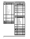
Example Address calculations
Program 1, Segment 4, Segment Type = 8328 + 32 + 0 = 8360 (20A8 Hex)
Program 2, Holdback Value = 8464 + 0 + 1 = 8465 (2111 Hex)
Program 4 Segment 16, End Type = 8872 + 128 + 3 = 9003 (232B Hex)
Power Level in End Segment
This has the tag address 64 in 2400
f
controllers.
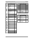
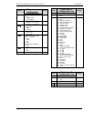
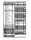
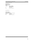
Summary of Programmer Enumerators
Controller Display Parameter Description
Current Segment Type
0: End
1: Ramp (Rate)
2: Ramp (Time to target)
3: Dwell
4: Step
5: Call
End Segment Type
0: Reset
1: Indefinate Dwell
2: Set Output
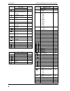
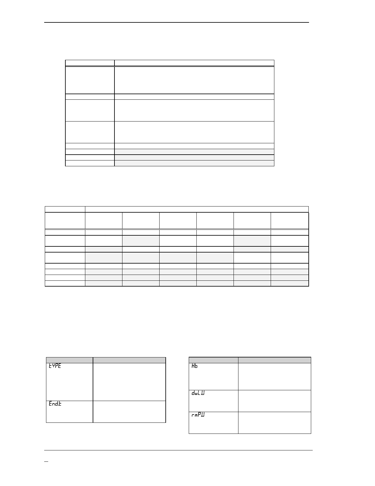
Controller Display Parameter Description
Holdback Type
0: None
1: Low
2: High
3: Band
Dwell Units
0: Seconds
1: Minutes
2: Hours
Ramp Units
0: Seconds
1: Minutes
2: Hours