


F940GOT-SWD-E/LWD-E Installation, Wiring and General Specifications 2.
2-21
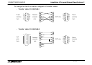
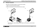
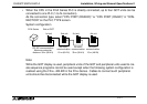
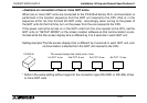
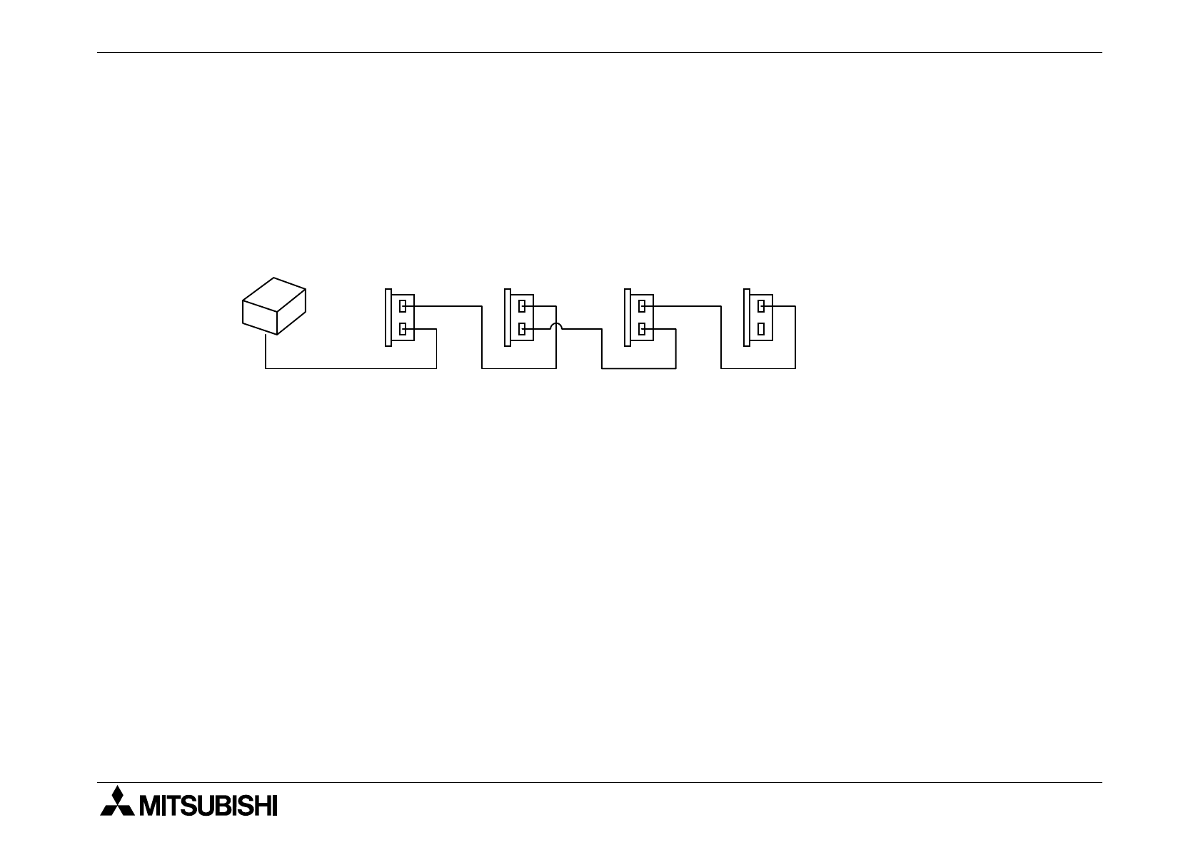
• When the CPU in the FX/A Series PLC is directly connected, up to four GOT units can be
connected to one PLC (1-to-N connection).
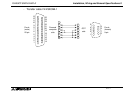
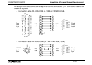
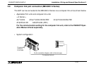
As the connection type, select "CPU PORT (RS232C)" or "CPU PORT (RS422)" in "CON-
NECTION" on the PLC TYPE screen.
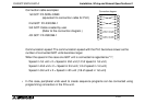
System configuration
Note:
While the GOT display is used, peripheral units of the GOT and peripheral units used to cre-
ate sequence programs cannot be used except when the following system configuration is
realized using the FX
2N
-422-BD in the FX
2N
Series. Cables to connect such peripheral
units should be disconnected while the GOT display is used.
RS-232C
communication
15 m (49.2ft)
1st unit 2nd unit 3rd unit 4th unit
RS-422 communication
Maximum extension
distance: 30 m (98.4 ft)
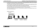
Side of GOTFX/A Series
RS-422C
communication
30 m (98.4 ft)
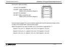
RS-232C
communication
15 m (49.2 ft)