


56
DataTalker Owner’s Manual
5.1 Introduction
This chapter describes how to connect the DataTalker to your system (Table 5-1) and how to
move the RS232/V.35 shunt when a V.35 interface is used (Table 5-2). Then it describes how to
power on your DataTalker, check that the unit is cabled and configured correctly, and what to do if
you run into problems.
5.2 Cabling
Connecting the DataTalker to your system requires two to four cables, depending on how you
intend to use the DataTalker. Each cable connection will be explained in detail in the following
procedures. When you cable the unit, you should consider how you configured it in Chapter 4.
For instance, if you configured the unit for a sync data channel, you cannot connect a standard
RS232C cable to the DATA/COMMAND connector on the back of the DataTalker. The following
cabling procedures relate the cables to the configuration.
Table 5-1. Cabling Procedure
Step Procedure
Composite Link
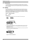
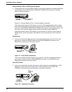
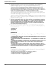
1 Verify that DIP switch position 2 is set for the composite link device being used:
Device DIP Switch 2
Internal OPEN (Up)
External Closed (Down)
MODEM
DSU/TA
DIAL-UP LEASED DIGITAL
VOICE/FAX CHANNEL 1
FXO FXS
EXTERNAL COMPOSITE
DATA/COMMAND
RS232C/V.35
E&M
INTERNAL COMPOSITE
POWER
GND
DIP
Switch
Figure 5-1. DIP Switches
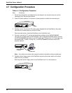
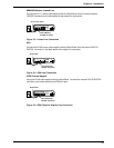
2 If you are using your DataTalker with an internal composite link device, connect one of the
two phone cables supplied with your unit to the appropriate internal composite connector:
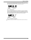
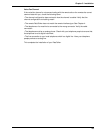
MMH2834 Modem, Dial-up
Connect the RJ-11 phone cable supplied with the DataTalker from the internal modem DIAL-
UP jack on the back panel to the dial-up line jack.
MODEM
DSU/TA
DIAL-UP LEASED DIGITAL
VOICE/FAX CHANNEL 1
FXO FXS
EXTERNAL COMPOSITE
DATA/COMMAND
RS232C/V.35
E&M
INTERNAL COMPOSITE
POWER
GND
Internal Modem
DIAL-UP Connector
RJ-11 Phone Cable
Figure 5-2. Dial-Up Line Connection