


Chapter 2 Configuring and Installing the SCXI Chassis
SCXI Chassis User Manual 2-8 ni.com
Configuring the SCXI Chassis
Configuring the chassis involves selecting a chassis or high-level data link
control (HDLC) address, line voltage, and fuse value on any chassis.
Note Refer to the Read Me First: Safety and Radio-Frequency Interference document
before removing equipment covers or connecting or disconnecting any signal wires.
Selecting Chassis Addresses
These sections provide information about how to select addresses for the
SCXI chassis.
SCXI-1000/1001
Unless you are using multiple chassis and need to configure one or more
SCXI chassis for a different address, you can skip this section, and the
SCXI chassis retains factory-default address of 0.
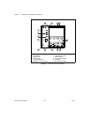
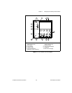
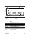
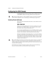
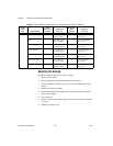
You can configure the SCXI chassis for one of 32 different addresses so that
you can connect multiple SCXI chassis to the same control source. The five
switches on the front panel of Slot 0 determine the chassis address.
Switches one through five represent the values 1, 2, 4, 8, and 16, when set
to the ON position. When set to the OFF position, their value is zero. The
chassis address is the sum of the switch values. Figure 2-7 shows examples
of both the factory-default setting of the chassis address 0 and the switch
setting for chassis address 19.
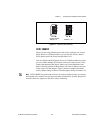
Note SCXI-1000 chassis through revision D do not have address jumpers or switches and
respond to any address, but you cannot use them in multichassis systems. Revision E
chassis use jumpers on Slot 0 for chassis addressing. Revision F and later chassis use a DIP
switch for chassis addressing.
SCXI-1001 chassis through revision D use jumpers on Slot 0 for chassis addressing.
Revision E and later chassis use a DIP switch for chassis addressing.