


Chapter 2 Configuring and Installing the SCXI Chassis
© National Instruments Corporation 2-13 SCXI Chassis User Manual
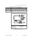
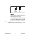
Replacing the Power Entry Module Fuse
Caution Disconnect all power before removing the cover.
Complete the following steps to replace the power entry module fuse:
1. Power off the chassis.
2. Remove the power cord from the power entry module.
3. Using a flathead screwdriver, pry the door to the voltage selection
tumbler open from the top.
4. Pull out the fuse drawer.
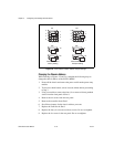
5. Remove the fuse.
6. Install the new fuse in the drawer.
7. Reinsert the fuse drawer in the right-hand slot with the arrow pointing
to the right.
8. Close the door.
9. Reinsert the power cord.
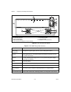
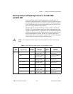
Replacing and Checking Backplane Fuses on the
SCXI-1000 and SCXI-1001
In addition to the power entry module fuse, the analog supply lines on the
backplane are fused at 1.5 A on the SCXI-1000 chassis and at 4 A on the
SCXI-1001 chassis.
If you are making your own modules, fuse the module at 250 mA to avoid
blowing the backplane fuses. Fusing the module also better protects the
module because a failure can result in a large amount of current drawn, but
not enough current drawn to blow the backplane fuses.
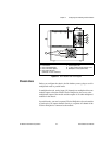
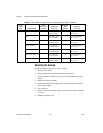
On the SCXI-1000, the backplane fuses are located behind the fan. On the
SCXI-1001, the backplane fuses are located behind the right-hand fan, near
the power entry module, as viewed from the rear of the chassis.