


Chapter 2 Configuring and Installing the SCXI Chassis
© National Instruments Corporation 2-15 SCXI Chassis User Manual
6. Push the fuse holder back into the housing and screw it clockwise until
it is tight.
7. Reinsert the power cord.
Replacing and Checking Backplane Fuses
In addition to the power entry and the +5 V supply fuses, the analog supply
lines on the backplane are fused at 1.5 A on the SCXI-1000DC chassis.
If you design a special/prototype module, use the SCXI-1181 module and
fuse the module at 250 mA to avoid blowing the analog backplane and
+5 V supply fuses. Fusing the module better protects the module because a
failure can result in a large amount of current drawn, but not enough to blow
the backplane and +5 V fuses.
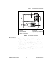
On the SCXI-1000DC, the backplane fuses are located behind the fan.
Complete the following steps to check or replace fuses:
1. Remove the appropriate fan and filter from the rear of the chassis by
following the instructions in the Maintaining the Fan Filter section.
Be sure to switch the power off and remove the power cord.
2. The fuse marked with a copper + on the backplane is for the positive
analog supply, and the fuse marked with a copper – is for the negative
analog supply. To check whether a fuse is blown, connect an ohmmeter
across the leads. If the reading is not approximately 0 Ω, replace the
fuse.
3. Using a pair of needle-nose pliers, carefully extract the fuse.
4. Take a new fuse and bend its leads so the component is 12.7 mm
(0.5 in.) long, the dimension between the fuse sockets, and clip the
leads to a length of 6.4 mm (0.25 in.).
5. Using the needle-nose pliers, insert the fuse into the socket holes.
6. Repeat, if necessary, for the other fuse.
7. Check the fan filter and, if it is dirty, clean it as described in the
Maintaining the Fan Filter section.
8. Reinstall the fan and filter.