


Chapter 7 Counters
© National Instruments Corporation 7-27 NI 6232/6233 User Manual
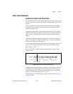
Counter n Source Signal
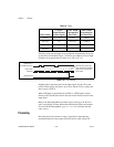
The selected edge of the Counter n Source signal increments and
decrements the counter value depending on the application the counter is
performing. Table 7-3 lists how this terminal is used in various
applications.
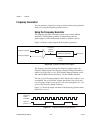
Routing a Signal to Counter n Source
Each counter has independent input selectors for the Counter n Source
signal. Any of the following signals can be routed to the Counter n Source
input.
•80MHz Timebase
•20MHz Timebase
• 100 kHz Timebase
•RTSI<0..7>
• Input PFI <0..5>
•PXI_CLK10
•PXI_STAR
In addition, Counter 1 TC or Counter 1 Gate can be routed to
Counter 0 Source. Counter 0 TC or Counter 0 Gate can be routed to
Counter 1 Source.
Some of these options may not be available in some driver software.
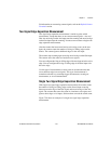
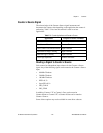
Table 7-3. Counter Applications and Counter n Source
Application Purpose of Source Terminal
Pulse Generation Counter Timebase
One Counter Time Measurements Counter Timebase
Two Counter Time Measurements Input Terminal
Non-Buffered Edge Counting Input Terminal
Buffered Edge Counting Input Terminal
Two-Edge Separation Counter Timebase