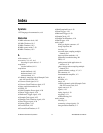
Index
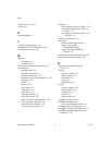
NI 6232/6233 User Manual I-2 ni.com
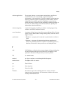
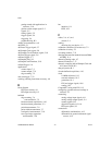
getting started with applications in
software, 5-10
glitches on the output signal, 5-2
signals, 5-5
timing signals, 5-5
trigger signals, 5-4
triggering, 5-4
troubleshooting, B-3
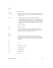
ANSI C documentation, xviii
AO FIFO, 5-1
AO Pause Trigger signal, 5-7
AO Sample Clock signal, 5-8
AO Sample Clock Timebase signal, 5-10
AO Start Trigger signal, 5-6
ao/PauseTrigger, 5-7
ao/SampleClock, 5-8
ao/SampleClockTimebase, 5-10
ao/StartTrigger, 5-6
applications
counter input, 7-3
counter output, 7-21
edge counting, 7-3
arm start trigger, 7-32
avoiding scanning faster than necessary, 4-9
B
block diagram
PFI input circuitry, 8-1
PFI output circuitry, 8-2
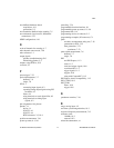
buffered
edge counting, 7-4
non-cumulative, 7-5
hardware-timed acquisitions, 4-10
hardware-timed generations, 5-3
period measurement, 7-8
pulse-width measurement, 7-7
semi-period measurement, 7-10
two-signal edge-separation
measurement, 7-20
bus
interface, 11-1
RTSI, 10-3
C
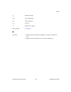
cables, 2-4, A-3, A-6
custom, 2-4
cabling
choosing for your device, 1-2
calibration certificate (NI resources), C-2
calibration circuitry, 2-3
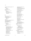
cascading counters, 7-33
changing data transfer methods between DMA
and IRQ, 11-4
channel scanning order, 4-7
channel Z behavior, 7-17
channels, sampling with AI Sample Clock and
AI Convert Clock, B-2
charge injection, B-1
circular-buffered acquisition, 4-10
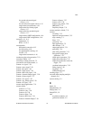
clock
10 MHz reference, 10-3
external reference, 10-2
generation, 10-1
PXI, and trigger signals, 10-8
routing, 10-1
CompactPCI, using with PXI, 11-3
configuring, ground-reference settings in
software, 4-3
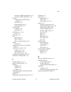
connecting
analog voltage input signals, 4-11
analog voltage output signals, 5-4
counter signals, B-3
digital I/O signals, 6-2, 8-6
PFI input signals, 8-3
connections
differential considerations, 4-13
differential for ground-referenced signal
sources, 4-14


