


Chapter 7 Counters
NI 6232/6233 User Manual 7-8 ni.com
of rising (or falling) edges occurring on the Source input between the two
active edges of the Gate signal.
You can calculate the period of the Gate input by multiplying the period of
the Source signal by the number of edges returned by the counter.
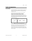
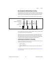
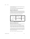
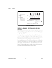
Single Period Measurement
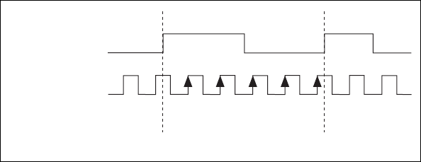
With single period measurement, the counter counts the number of rising
(or falling) edges on the Source input occurring between two active edges
of the Gate input. On the second active edge of the Gate input, the counter
stores the count in a hardware save register and ignores other edges on the
Gate and Source inputs. Software then can read the stored count.
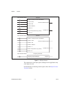
Figure 7-8 shows an example of a single period measurement.
Figure 7-8. Single Period Measurement
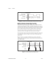
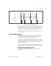
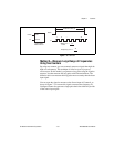
Buffered Period Measurement
Buffered period measurement is similar to single period measurement, but
buffered period measurement measures multiple periods.
The counter counts the number of rising (or falling) edges on the Source
input between each pair of active edges on the Gate input. At the end of
each period on the Gate signal, the counter stores the count in a hardware
save register. A DMA controller transfers the stored values to host memory.
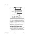
The counter begins when it is armed. The arm usually occurs in the middle
of a period of the Gate input. So the first value stored in the hardware save
register does not reflect a full period of the Gate input. In most applications,
this first point should be discarded.
Figure 7-9 shows an example of a buffered period measurement.
SOURCE
GATE
Counter Value
HW Save Register
103
5
4
5
2