


© National Instruments Corporation 4-1 NI 6232/6233 User Manual
4
Analog Input
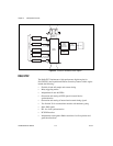
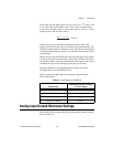
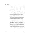
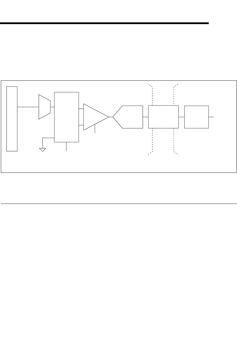
Figure 4-1 shows the analog input circuitry of NI 6232/6233 devices.
Figure 4-1. NI 6232/6233 Analog Input Circuitry
Analog Input Circuitry
I/O Connector
You can connect analog input signals to the M Series device through the I/O
connector. The proper way to connect analog input signals depends on the
analog input ground-reference settings, described in the Analog Input
Ground-Reference Settings section. Also refer to Appendix A,
Device-Specific Information, for device I/O connector pinouts.
MUX
Each M Series device has one analog-to-digital converter (ADC). The
multiplexers (MUX) route one AI channel at a time to the ADC through the
NI-PGIA.
DIFF,
RSE,
or NRSE
I/O Connector
AI <0..
n
>
Mux
AI GND
NI-PGIA
AI Terminal
Configuration
Selection
Input Range
Selection
ADC
AI Data
Isolation
Barrier
Digital
Isolators
AI FIFO