


Chapter 6 Digital Input and Output
NI 6232/6233 User Manual 6-2 ni.com
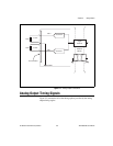
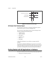
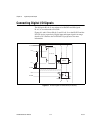
Connecting Digital I/O Signals
The DI signals P0.<0..5> are referenced to P0.GND and DO signals
P1.<0..3> are referenced to P1.GND.
Figures 6-1 and 6-2 show P0.<0..5> and P1.<0..3> on the NI 6232 and the
NI 6233 device, respectively. Digital input and output signals can range
from 0 to 30 V. Refer to the NI 6232/6233 Specifications for more
information.
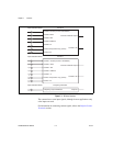
Figure 6-1. NI 6232 Digital I/O Connections (DO Source)
P1.<0..3>
P1.VCC
P1.0
P1.1
P1.GND
P0.0
P0.GND
P1.GND
P0.GND
Digital
Isolators